1. In diagrams a) through d) show how much of the 100 MW flows in each path. 100 MW 100 100 MW a) 100 100MW 100 MW b) 100 ΤΟ Ω 100MW c) 100 MW 20 Ω 100 100 MW 200 100 MW d) 200 HINT: XL XL/2 XL
1. In diagrams a) through d) show how much of the 100 MW flows in each path. 100 MW 100 100 MW a) 100 100MW 100 MW b) 100 ΤΟ Ω 100MW c) 100 MW 20 Ω 100 100 MW 200 100 MW d) 200 HINT: XL XL/2 XL

Delmar's Standard Textbook Of Electricity
7th Edition
ISBN:9781337900348
Author:Stephen L. Herman
Publisher:Stephen L. Herman
Chapter22: Resistive-capacitive Parallel Circuits
Section: Chapter Questions
Problem 6RQ: Refer to the formulas in Appendix B in the Resistive-Capacitive Parallel Circuits section. A...

Related questions
Question
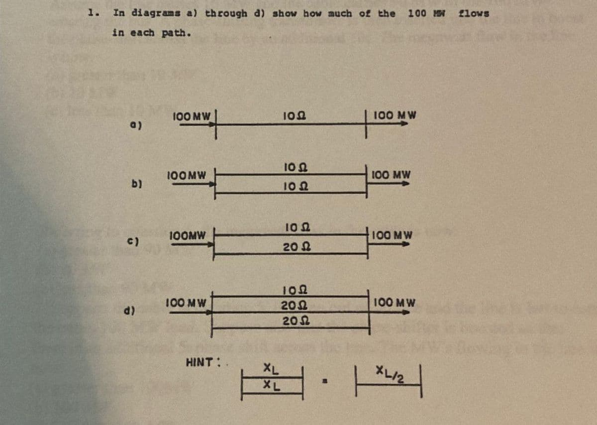
Transcribed Image Text:1.
In diagrams a) through d) show how much of the 100 MW flows
in each path.
100 MW
100
100 MW
a)
100
100MW
100 MW
b)
100
ΤΟ Ω
100MW
c)
100 MW
20 Ω
100
100 MW
200
100 MW
d)
200
HINT:
XL
XL/2
XL
Expert Solution
This question has been solved!
Explore an expertly crafted, step-by-step solution for a thorough understanding of key concepts.

Step by step
Solved in 2 steps with 4 images

Recommended textbooks for you
Delmar's Standard Textbook Of Electricity
Electrical Engineering
ISBN:
9781337900348
Author:
Stephen L. Herman
Publisher:
Cengage Learning
Delmar's Standard Textbook Of Electricity
Electrical Engineering
ISBN:
9781337900348
Author:
Stephen L. Herman
Publisher:
Cengage Learning