1. Report the experimental välües of a. The current through R1 b. The current through R2 C. The current through R3 d. Total current through the circuit 2. Report the experimental voltage drop/ the voltage difference across a. Resistor R1 (Note the voltage drop for R1 6V-reading on voltmeter 1) b. Resistor R2 C. Resistor R3 3. Using Ohm's law and the values specified in the circuit, calculate a. The equivalent resistance and the total current through the circuit b. The voltage drop/the voltage difference across the resistor R1
1. Report the experimental välües of a. The current through R1 b. The current through R2 C. The current through R3 d. Total current through the circuit 2. Report the experimental voltage drop/ the voltage difference across a. Resistor R1 (Note the voltage drop for R1 6V-reading on voltmeter 1) b. Resistor R2 C. Resistor R3 3. Using Ohm's law and the values specified in the circuit, calculate a. The equivalent resistance and the total current through the circuit b. The voltage drop/the voltage difference across the resistor R1

Introductory Circuit Analysis (13th Edition)
13th Edition
ISBN:9780133923605
Author:Robert L. Boylestad
Publisher:Robert L. Boylestad
Chapter1: Introduction
Section: Chapter Questions
Problem 1P: Visit your local library (at school or home) and describe the extent to which it provides literature...

Related questions
Question
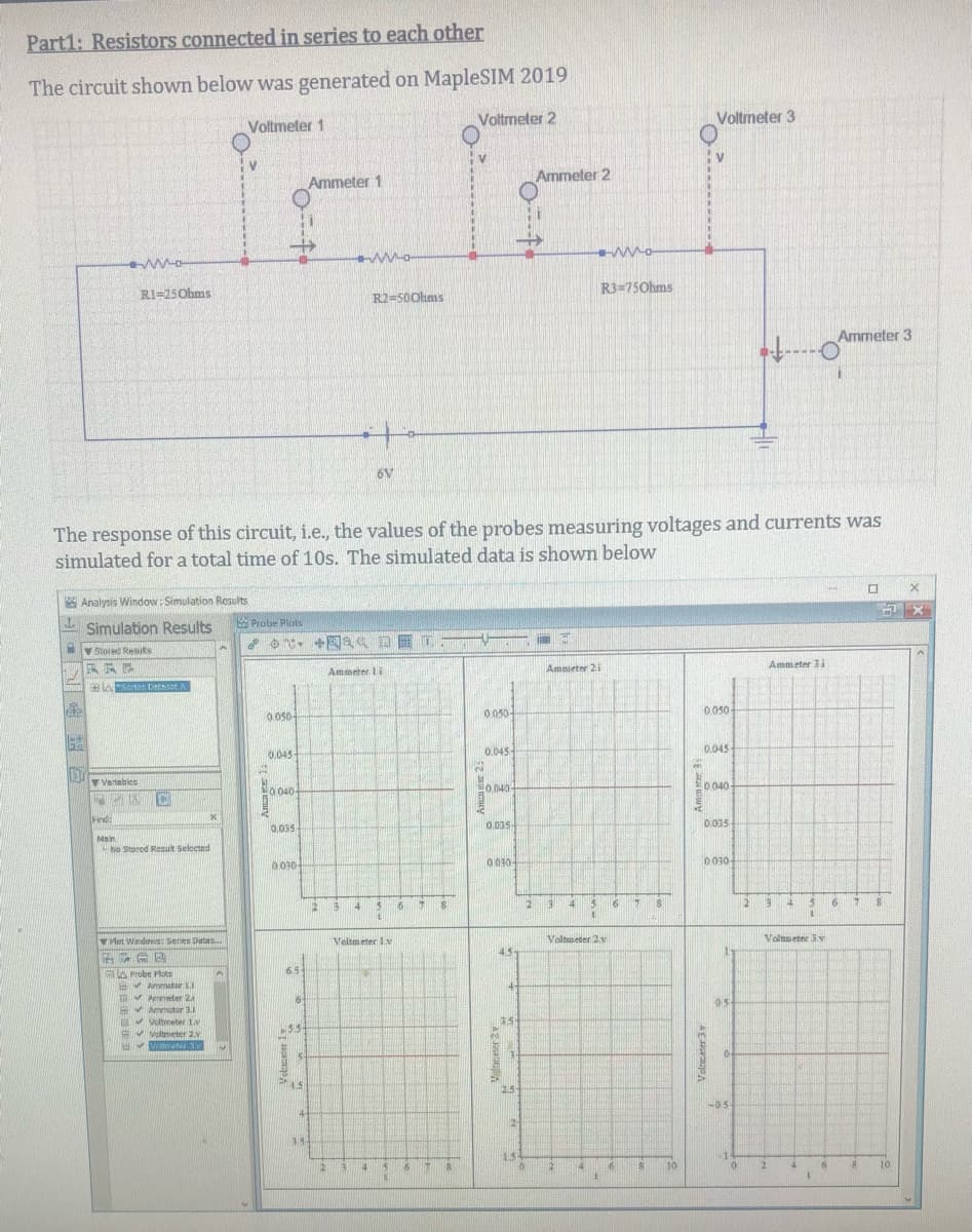
Transcribed Image Text:Part1: Resistors connected in series to each other
The circuit shown below was generated on MapleSIM 2019
Voltmeter 1
Voltmeter 2
Voltmeter 3
Ammeter 2
Ammeter 1
RI=25Ohms
R2=500hms
R3=750hms
Ammeter 3
6V
The response of this circuit, i.e., the values of the probes measuring voltages and currents was
simulated for a total time of 10s. The simulated data is shown below
* Analysis Window: Simulation Results
E Probe Pluts
- Simulation Results
V Stored Results
Ammeter 3i
Ammeter li
Ammeter 21
0.050
0 050-
0 050-
0.045
0.045
0.045-
Vanables
0 040
O 040
0 040
Find
0.035-
0.035
0.035-
Main
No Stored Resut Selected
0030-
0030
0 030
16
41
16
2
6 7 8
Hot Windovs Senes Datas.
Veltmeter 1v
Valtmeter 2y
Volmeter 3.v
4.5-
65
ala Probe Plots
E Ammeter J
E Aeter 2a
B Ammotor 3.1
E Voltmeter 1v
Av voltmeter Z.v
05
3.5
Vettreeter 3.N
1.5
25
-05-
-0.5
14-
21
1.5
12
10
12
10
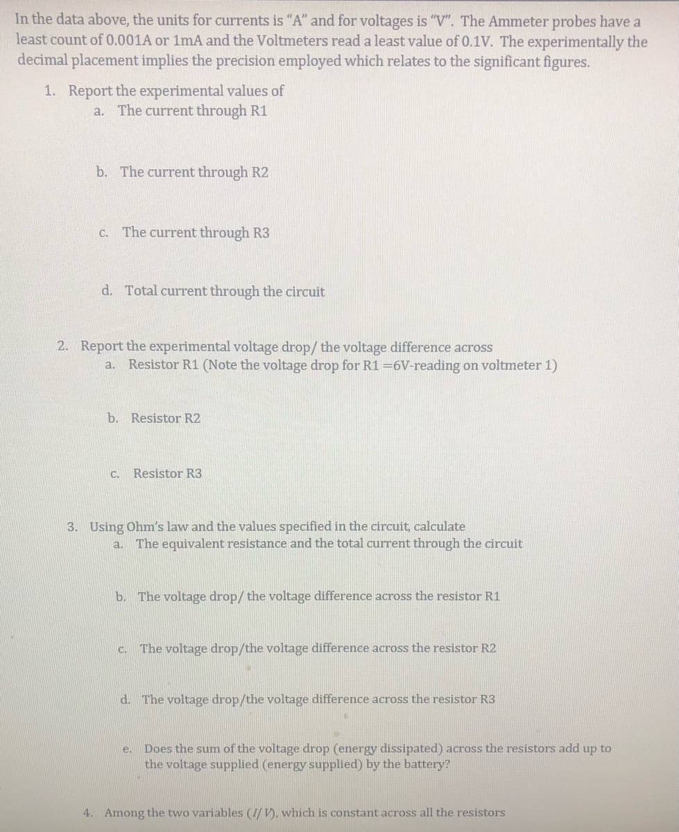
Transcribed Image Text:In the data above, the units for currents is "A" and for voltages is "V". The Ammeter probes have a
least count of 0.001A or 1mA and the Voltmeters read a least value of 0.1V. The experimentally the
decimal placement implies the precision employed which relates to the significant figures.
1. Report the experimental values of
a. The current through R1
b. The current through R2
C. The current through R3
d. Total current through the circuit
2. Report the experimental voltage drop/ the voltage difference across
Resistor R1 (Note the voltage drop for R1 =6V-reading on voltmeter 1)
a.
b. Resistor R2
C.
Resistor R3
3. Using Ohm's law and the values specified in the circuit, calculate
a. The equivalent resistance and the total current through the circuit
b. The voltage drop/ the voltage difference across the resistor R1
The voltage drop/the voltage difference across the resistor R2
d. The voltage drop/the voltage difference across the resistor R3
Does the sum of the voltage drop (energy dissipated) across the resistors add up to
the voltage supplied (energy supplied) by the battery?
e.
4. Among the two variables (I/ V), which is constant across all the resistors
Expert Solution
This question has been solved!
Explore an expertly crafted, step-by-step solution for a thorough understanding of key concepts.

Step by step
Solved in 2 steps with 1 images

Recommended textbooks for you
Introductory Circuit Analysis (13th Edition)
Electrical Engineering
ISBN:
9780133923605
Author:
Robert L. Boylestad
Publisher:
PEARSON

Delmar's Standard Textbook Of Electricity
Electrical Engineering
ISBN:
9781337900348
Author:
Stephen L. Herman
Publisher:
Cengage Learning

Programmable Logic Controllers
Electrical Engineering
ISBN:
9780073373843
Author:
Frank D. Petruzella
Publisher:
McGraw-Hill Education
Introductory Circuit Analysis (13th Edition)
Electrical Engineering
ISBN:
9780133923605
Author:
Robert L. Boylestad
Publisher:
PEARSON
Delmar's Standard Textbook Of Electricity
Electrical Engineering
ISBN:
9781337900348
Author:
Stephen L. Herman
Publisher:
Cengage Learning
Programmable Logic Controllers
Electrical Engineering
ISBN:
9780073373843
Author:
Frank D. Petruzella
Publisher:
McGraw-Hill Education

Fundamentals of Electric Circuits
Electrical Engineering
ISBN:
9780078028229
Author:
Charles K Alexander, Matthew Sadiku
Publisher:
McGraw-Hill Education

Electric Circuits. (11th Edition)
Electrical Engineering
ISBN:
9780134746968
Author:
James W. Nilsson, Susan Riedel
Publisher:
PEARSON

Engineering Electromagnetics
Electrical Engineering
ISBN:
9780078028151
Author:
Hayt, William H. (william Hart), Jr, BUCK, John A.
Publisher:
Mcgraw-hill Education,