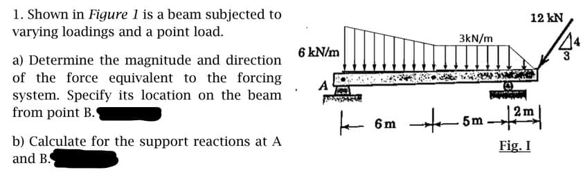
1. Shown in Figure 1 is a beam subjected to varying loadings and a point load. 12 kN 3kN/m 6 kN/m a) Determine the magnitude and direction of the force equivalent to the forcing system. Specify its location on the beam from point B. A 2 m m b) Calculate for the support reactions at A and B. Fig. I
1. Shown in Figure 1 is a beam subjected to varying loadings and a point load. 12 kN 3kN/m 6 kN/m a) Determine the magnitude and direction of the force equivalent to the forcing system. Specify its location on the beam from point B. A 2 m m b) Calculate for the support reactions at A and B. Fig. I

Chapter9: Application Of Influence Lines
Section: Chapter Questions
Problem 2P

Related questions

Question
Transcribed Image Text:1. Shown in Figure 1 is a beam subjected to
varying loadings and a point load.
12 kN
3kN/m
6 kN/m
a) Determine the magnitude and direction
of the force equivalent to the forcing
system. Specify its location on the beam
from point B.
A
5m
b) Calculate for the support reactions at A
and B.
Fig. I
Expert Solution
This question has been solved!
Explore an expertly crafted, step-by-step solution for a thorough understanding of key concepts.

Step by step
Solved in 2 steps

Knowledge Booster


Learn more about
Need a deep-dive on the concept behind this application? Look no further. Learn more about this topic, civil-engineering and related others by exploring similar questions and additional content below.Recommended textbooks for you