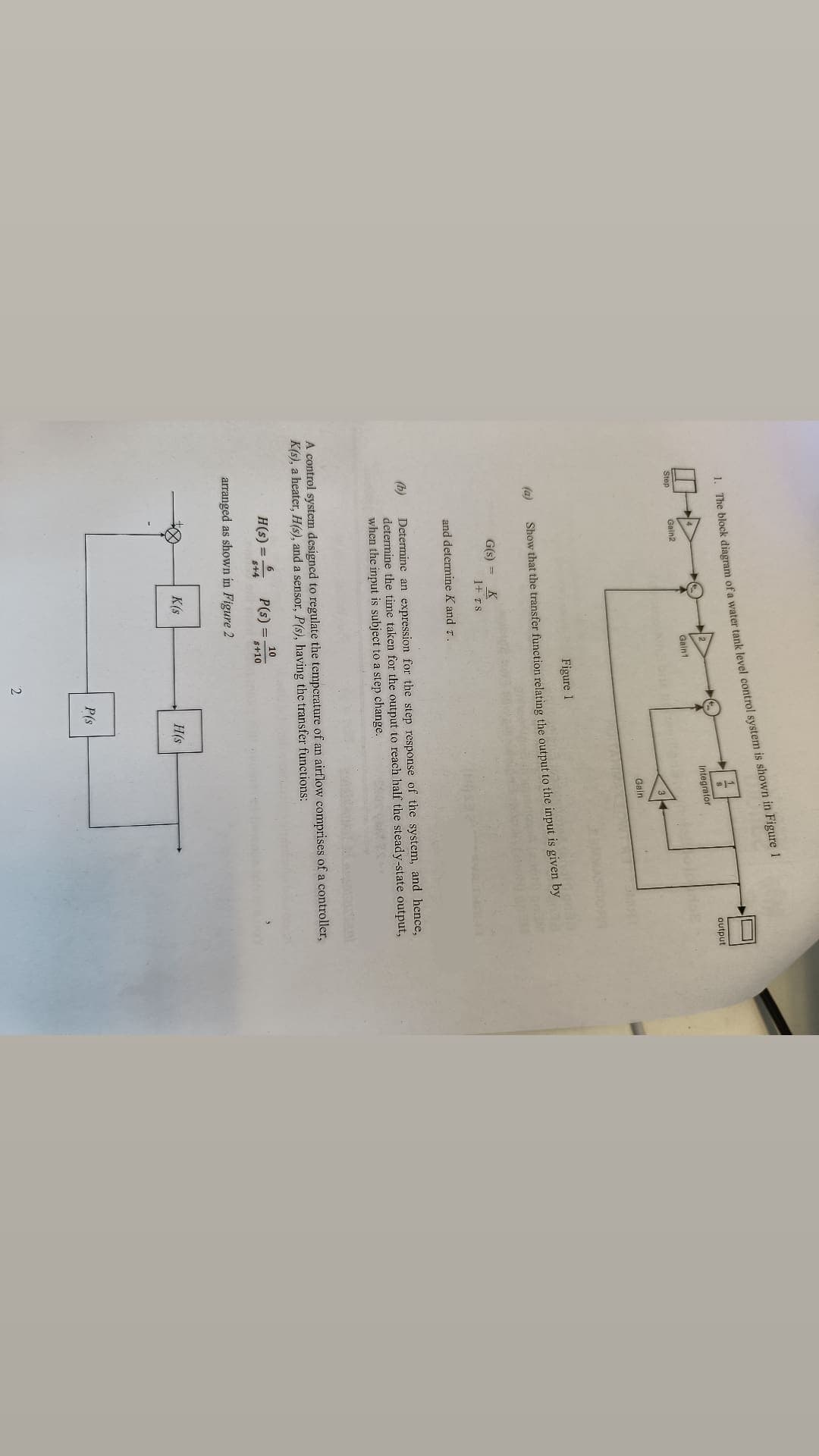
1. The block diagram of a water tank level control system is shown in Figure 1 Integrator Gaint Gain2 Step Gain Figure 1 Show that the transfer function relating the output to the input is given by G(s) = K 1+ TS and determine K and T. (b) Determine an expression for the step response of the system, and hence, determine the time taken for the output to reach half the steady-state output, when the input is subject to a step change. output


Protection System
A system that protects electrical systems from faults by isolating the problematic part from the remainder of the system, preventing power from being cut from healthy elements, improving system dependability and efficiency is the protection system. Protection devices are the equipment that are utilized to implement the protection system.
Predictive Maintenance System
Predictive maintenance technologies are designed to assist in determining the state of in-service equipment so that maintenance can be scheduled. Predictive maintenance is the application of information; proactive maintenance approaches examine the condition of equipment and anticipate when it should maintain. The purpose of predictive maintenance is to forecast when equipment will fail (depending on a variety of parameters), then prevent the failure through routine and corrective maintenance.Condition monitoring is the continual monitoring of machines during process conditions to maintain optimal machine use, which is necessary for predictive maintenance. There are three types of condition monitoring: online, periodic, and remote. Finally, remote condition monitoring allows the equipment observed from a small place and data supplied for analysis.
Preventive Maintenance System
To maintain the equipment and materials on a regular basis in order to maintain those running conditions and reduce unnecessary shutdowns due to unexpected equipment failure is called Preventive Maintenance (PM).
Can you do part b please

Step by step
Solved in 2 steps with 2 images


