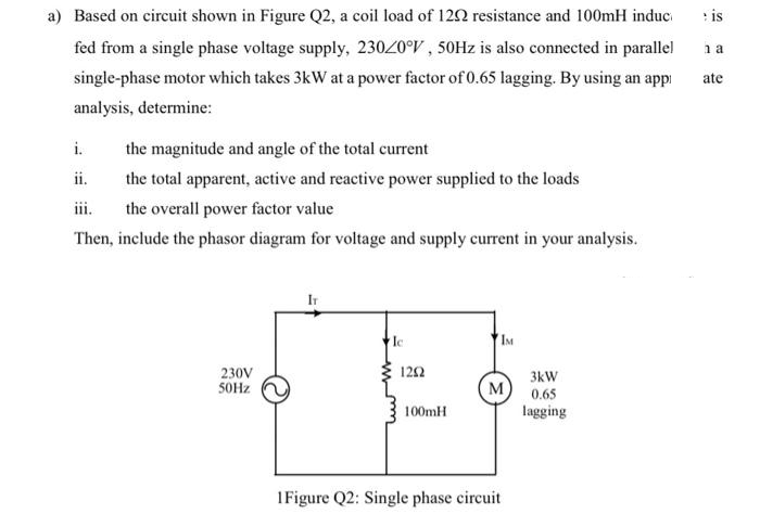
is na a) Based on circuit shown in Figure Q2, a coil load of 1202 resistance and 100mH induc fed from a single phase voltage supply, 230/0°V, 50Hz is also connected in parallel single-phase motor which takes 3kW at a power factor of 0.65 lagging. By using an appi analysis, determine: ate i. the magnitude and angle of the total current ii. the total apparent, active and reactive power supplied to the loads iii. the overall power factor value Then, include the phasor diagram for voltage and supply current in your analysis. Ic IM 230V 50Hz 1202 M 100mH 1 Figure Q2: Single phase circuit 3kW 0.65 lagging
is na a) Based on circuit shown in Figure Q2, a coil load of 1202 resistance and 100mH induc fed from a single phase voltage supply, 230/0°V, 50Hz is also connected in parallel single-phase motor which takes 3kW at a power factor of 0.65 lagging. By using an appi analysis, determine: ate i. the magnitude and angle of the total current ii. the total apparent, active and reactive power supplied to the loads iii. the overall power factor value Then, include the phasor diagram for voltage and supply current in your analysis. Ic IM 230V 50Hz 1202 M 100mH 1 Figure Q2: Single phase circuit 3kW 0.65 lagging

Power System Analysis and Design (MindTap Course List)
6th Edition
ISBN:9781305632134
Author:J. Duncan Glover, Thomas Overbye, Mulukutla S. Sarma
Publisher:J. Duncan Glover, Thomas Overbye, Mulukutla S. Sarma
Chapter2: Fundamentals
Section: Chapter Questions
Problem 2.21P: An industrial plant consisting primarily of induction motor loads absorbs 500 kW at 0.6 power factor...

Related questions

Question
Transcribed Image Text:is
na
a) Based on circuit shown in Figure Q2, a coil load of 129 resistance and 100mH induc
fed from a single phase voltage supply, 230/0°V, 50Hz is also connected in parallel
single-phase motor which takes 3kW at a power factor of 0.65 lagging. By using an app
analysis, determine:
ate
i.
the magnitude and angle of the total current
ii.
the total apparent, active and reactive power supplied to the loads
the overall power factor value
Then, include the phasor diagram for voltage and supply current in your analysis.
Ic
IM
230V
50Hz
1202
M
100mH
1Figure Q2: Single phase circuit
3kW
0.65
lagging
Expert Solution
This question has been solved!
Explore an expertly crafted, step-by-step solution for a thorough understanding of key concepts.

Step by step
Solved in 2 steps with 3 images

Knowledge Booster


Learn more about
Need a deep-dive on the concept behind this application? Look no further. Learn more about this topic, electrical-engineering and related others by exploring similar questions and additional content below.Recommended textbooks for you
Power System Analysis and Design (MindTap Course …
Electrical Engineering
ISBN:
9781305632134
Author:
J. Duncan Glover, Thomas Overbye, Mulukutla S. Sarma
Publisher:
Cengage Learning
Power System Analysis and Design (MindTap Course …
Electrical Engineering
ISBN:
9781305632134
Author:
J. Duncan Glover, Thomas Overbye, Mulukutla S. Sarma
Publisher:
Cengage Learning