10 µF IN4004 Vs 310 k2 10 Vp-p 3 V 1 KIIZ Figure 5.6: Biased Negative Clamper
10 µF IN4004 Vs 310 k2 10 Vp-p 3 V 1 KIIZ Figure 5.6: Biased Negative Clamper

Chapter32: Two-speed, One-winding (consequent Pole) Motor Controllers
Section: Chapter Questions
Problem 6SQ: Describe the operation of Figure 325 (B) by adding jumper wire A to the original circuit.

Related questions

Question
Please don't copy the Answer from any other platform
Notice that should be Va=0
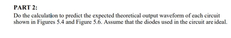
Transcribed Image Text:PART 2:
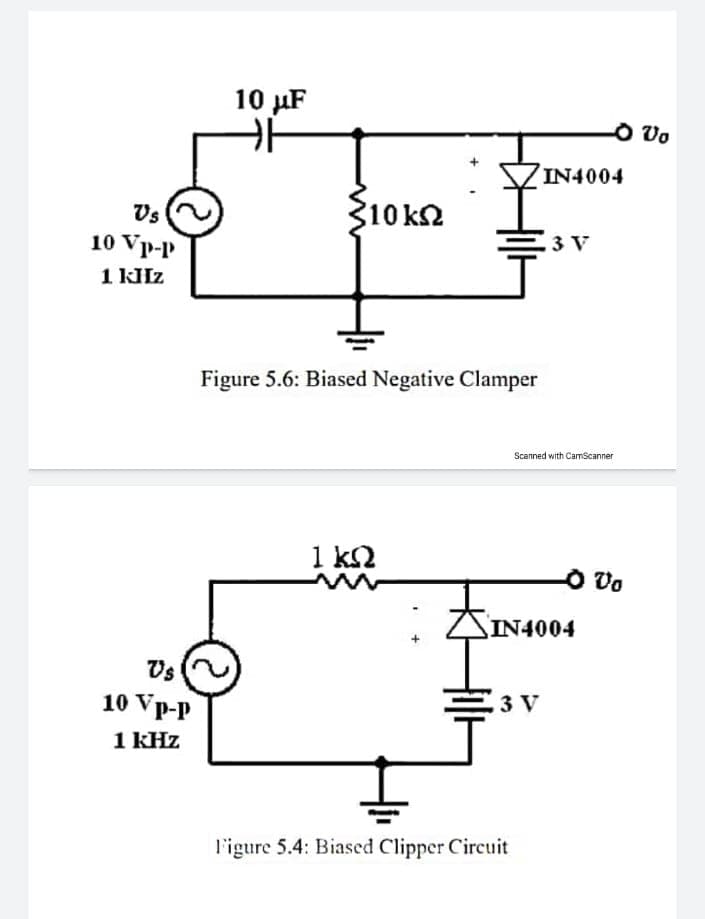
Do the calculation to predict the expected theoretical output waveform of each circuit
shown in Figures 5.4 and Figure 5.6. Assume that the diodes used in the circuit are ideal.
Transcribed Image Text:10 µF
O Vo
IN4004
Vs
310 k2
3 V
10 Vp-p
Figure 5.6: Biased Negative Clamper
Scanned with CamScanner
1 ΚΩ
O Vo
SIN4004
Vs
10 Vp-p
3 V
1 kHz
l'igure 5.4: Biased Clipper Circuit
Expert Solution
This question has been solved!
Explore an expertly crafted, step-by-step solution for a thorough understanding of key concepts.

Step by step
Solved in 2 steps with 4 images

Knowledge Booster


Learn more about
Need a deep-dive on the concept behind this application? Look no further. Learn more about this topic, electrical-engineering and related others by exploring similar questions and additional content below.Recommended textbooks for you