10. The input to the circuit shown in the figure is the voltage vs(t) = 12 cos(4000t) V. The output is the capacitor voltage vo(t). Determine vo(t). 150 ia 100 Ω www 200 Ω la + 20 uF Vo - t=0 25 Ω
Q: [V₁ V₂ V3 = if an impedance of value j0.4 is added between bus 2 and bus 4, then Z₁1 of the updated…
A: Z bus is known as bus impedance matrix in power system. Z bus is equal to the inverse of the…
Q: ask 7 Examine the P, I, and D parameters on the dynamic responses of the transfer functions in…
A:
Q: The time available to turn-off thyristor in load-commutated chopper is 3-2E2Cf, 4-C, 5- None of…
A: The above question is based on load commutated chopper.
Q: The diagram below shows a DC circuit containing resistors. State your answers to two significant…
A:
Q: A 10 resistor and a 5 μF capacitor are connected in parallel. This parallel combination is also in…
A:
Q: (iv) Use state diagrams to illustrate all of the possible sequences that a 4-stage ring counter…
A:
Q: Q-Select the correct answer: a- The time ts of a voltage commutated chopper is 2-2π√√LC, 3-0.5√/LmC,…
A: “Since you have posted a question with multiple sub parts, we will provide the solution only to the…
Q: E₁ + R₁ ww 7 V IG +0 a 1₁ V ab R₂ + + E₂ Given that E₁ = 9.5V, E₂ = 2.8V, R₁ = 9760 and R₂ = 2650,…
A: E1 = 9.5 V E2 = 2.8 V R1 = 976 ohm R2 = 265 ohm
Q: Three long, straight conductors are placed as shown in Figure and they carry a current of 3 A each.…
A:
Q: R(S) + G₁ + G₂ H₁ I G3 I H3 I H₂ 2 G4
A: Given Data:A block diagram of a system with,Input Output To Find:The transfer function
Q: 1 - Design a counter using a 74HC163 binary counter MOD is 15 and use LD to design. 2- Draw the…
A: Need to design a MOD 15 counter by using the IC 74163. The reset of the counter should be carried…
Q: Find to in the circuit of fig. 5, given the source is 540⁰A. j4n2 22 M -jan- -m- -j2n= Fig. 5 I. H↓…
A: Current divider rule:
Q: Vs RE M Rc1 Q₁ M Vcc Rc2 Q₂ M RE Q3 -O V₂ Sketch the feedback small signal model of this circuit.
A: For a small signal circuit DC voltage sources (Vcc) are grounded and DC Current sources are open…
Q: Suppose that we modulate the periodic message signal m(t) given in the figure by PM modulation with…
A: Solution:Given Data:= harmonicFind:Here find bandwidth of modulated signal.
Q: Question-2 ) The series impedance of a 200-mile, 60 Hz, three-phase transmission line is given as z…
A: “Since you have posted a question with multiple sub-parts, we will solve the first three sub-parts…
Q: Transformer Calculations 3.1 a Determine the amount of EMF induced in the primary and secondary…
A: Maximum magnetic flux induced Frequency f = 60 Hz.Number of turns in primary Number of turns in…
Q: 11.17 Following are four successive approximations of tanh s. (a) 3s +3 Synthesize networks for the…
A: Given: Input Impedance of the network Z(s) = Aim:Synthesize the network from the given function
Q: 2. Determine the inverse z transform of X(z) = = 1+ 2z¹+z-² 1 3 -1 Z + Z-2 2 Also plot the poles and…
A: The pole is point at which the denominator of system become zero. The zero is point at which the…
Q: Question 2. The circuit has been in operation for a long time. At t-0, the two switches move to the…
A: Asked to findix(t) for t0vx(t) for t0
Q: Implement a full-adder circuit with a decoder and two OR gates.
A: Implementation of a full adder circuit with a decoder and two OR gates.
Q: In the circuit shown in (Figure 1), both switches operate together, that is, they either open or…
A: Given:A circuit, Before t=0, both the switches are closed for a long time. To do:a) Need to…
Q: 1) What is the name of the op amp circuits in the dashed box? 2) Explain briefly what is the purpose…
A: The above question is based on op-amp circuits.Since multiple subparts have been posted, as per…
Q: I1 R1 R2 WW R3 R4 b a-) Find the expression of the voltage v in the s-domain. V(s)= [Choose ] 1=0…
A: to find v(s) and v(t)
Q: 2. A sequential circuit with two D flip-flops A and B, two inputs X and Y, and one output Z is…
A:
Q: (c) A single-phase motor is connected to a 230 Vrms, 50 Hz power supply. The motor has a real power…
A:
Q: find f(t) using laplace transform. the given equation is d^2f/dt + 5*df/dt +4f = e^-2t*u(t)
A:
Q: Question 4. The switch in the figure is closed at t = 0. The initial voltage of the capacitor is 30…
A:
Q: For a BPSK modulator with a carrier frequency of 70 MHz and an input bit rate of 10 Mbps, determine…
A: The input bit rate is 10 Mbps.
Q: 7. 4.4-2. Consider the circuit shown below. Use Laplace transform techniques to solve the following:…
A: Solution:Given data :=> R=C=1=> x(t)==> Find :=> here find first standard form for…
Q: 3 substations A, B and C are spaced 75 km apart as shown in Figure, B and C are connected together…
A:
Q: 200 KVA, single phase two-winding transformer rated 4160/230 V, 60 Hz has primary and second…
A:
Q: reduce block diagram
A: The given block diagram should be reduced by using the block diagram reduction techniques to get the…
Q: In the figure below &1 = 6.00V, 82 = 12.00 V, R₁ = 100 2, R₂ = 300 , R3 = 2002, and both batteries…
A:
Q: 1 - Design a counter using a 74HC163 binary counter Determined by : MOD is 11 and use LD to design.…
A: Need to design a MOD 15 counter by using the IC 74163. The reset of the counter should be carried…
Q: Consider the circuit shown below, where K = 0.2 mA/V2 and Vto = 0.8V. 1) If V1 = 3V, what is the…
A: Since you have asked multiple questions, we will solve the first question for you. If you want any…
Q: A 200 KVA, single phase two-winding transformer rated 4160/ V, 60 Hz has primary and second…
A: We have to Answer the following questiona. The core loss at normal operation and the maximum and…
Q: (6) 3.- A 6-pole, 440V and 60 Hz three-phase induction motor operates with a slip of 0.05 and has an…
A: Given dataPole, Supply voltage, Supply frequency, Slip, Output power, Stator copper loss, Rotational…
Q: Calculate the time constant
A:
Q: A stationary random processes x (T) has the power spectral density function (w): 1 Sxx (@) = (4+²)2.…
A:
Q: A Thevenin equivalent can also be determined from measurements made at the pair of terminals of…
A:
Q: Group the terms in your KCL equations and rewrite your equations in terms of V₁, V2, V3 ..i.e, find…
A: Solution:Given data:Find :=>here apply KCL at Three nodes.
Q: 3. Implement switching function F (A, B, C) = A'B C' + B'C + AB' with a 4-to-1 multiplexer: show…
A:
Q: What is the capacitive reactance of the capacitor? Express your answer to three significant figures…
A:
Q: Consider the circuit shown in the figure below. The switch is kept in position (a) for long time,…
A: The circuit diagram is shown below,
Q: AC input A 220Vrms a = 15:2 Si I www. R₁ 800 ohms C DC output DC without capacitor DC with capacitor
A:
Q: g- In a single-phase full converter, for discontinuous load current and angle ß> π, each SCR…
A: to choose correct answer from the given options
Q: Q) X(t) = A (os (wt +Ø) where A is uniform IR.V. over (0,1) w and I are constant (a) auto…
A: Note: I am solving it in both formats handwritten as well as text typingGiven dataHere is a uniform…
Q: Q5- Find R out in the following circuit Rout VinM₁ M₂ V M2
A: Step-1->The relation between the channel length modulation parameter and drain to source…
Q: Calculate the required number of turbines we need in a wind farm generating 1MW if each turbine have…
A:
Q: 11 R2 R1 R3 R4 a b I+ L The switch, which has been in position a for a long time in the circuit…
A:
Please handwriting solution with clear and neat handwriting for like pls...
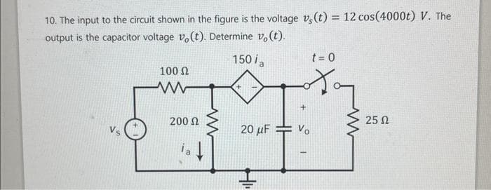
Step by step
Solved in 4 steps with 20 images
- given circuit, Vk = 12 V, R = 240 Ω, C = 1 μF, L = 40 mH. Theswitch, is closed for a long time for t < 0– . Determine vL(t) for t > 0.In the following circuit shown, the input is the independent source voltage, which is v_s (t) = 9.10 cos (3t + 80 °) V. The output is the voltage of the 5 ohm resistor, denoted by v_o (t). Determine the capacitance (C) and resistance (R), which cause the output voltage to be v_o (t) = 4.43 cos (3t + 93 °) V.The admittance for a circuit, G + jB, is 0.02 + j0.20. What is the impedance, R + jX? Provide illustration of the circuit.
- The current through a 0.5 F capacitor is i(t) = 6(1 - et) A, with-t in seconds. Determine the power in Watts at t = 2 s. Assume voltage at the start time of t = 0 is v(O) = 0.70. Ideal inductors and capacitors are 90 degrees out of phase with each other. True False 71. Ideal inductors and resistors are 180 degrees out of phase with each other. True False 72. Impedance of a circuit can be represented or expressed in complex form. True FalseA 6.36 μF capacitor is connected in parallel with a resistance of 500Ω and the combination is connected in series with a 500Ω resistor. The whole circuit is connected across an ac source given by e=300sin(ωt) + 100 sin(3ωt + 30°). If ω = 314 rad/s. find: a)Irms b)Vrms c)total active power d)total power factor e)total reactive power f)total apparent power
- a series rlc circuit having values of pure resistance r=40 ohms and pure inductance l = 50.07 mh. the circuit draws 10 A of current when it is connected across a 400 v , 50hz ,ac supply. calculate the (1) capacitor value and (2) power factor of circuit.A resistor'R' with resistance value of 24 ohm, an inductor 'L' with inductance 20mH, and a capacitor 'C' with capacitance 50 micro Farrad are connected in series with a AC voltage v(t) where v(t) = 50 cos (2 vt + 30 degrees) v. Determine the current i(t) and total impedance if the frequency f is i. 60 Hz ii. 400HzThe sinusoidal voltage source in the circuit isdeveloping a voltage equal to 50 sin 400t V.1. Find the Thévenin voltage with respect to the terminals a,b.2. Find the Thévenin impedance with respect to the terminals a,b.3. Draw the Thévenin equivalent
- For the circuit shown, determine:a) Plot pole-zero diagram for H = I / Vsb) Based on H, calculate the forced response for i (t) to an excitation:Vs (t) = 5 e-3tsin (50t) cos (60t) [V]In the circuit shown, the input is the independent source voltage, which is vs (t) = 9.10 cos (3t + 80 °) V. The output is the 5 resistor voltage, denoted by vo (t). Determine the capacitance C and the resistance R that cause the output voltage to be vo (t) = 4.43 cos (3t + 93 °) V.H5. An RCL circuit connected in series has R = 180 ohms, C = 1/280 farad, L = 20 henries, and an applied voltage E(t) = 10 sin t. Assuming no initial charge on the capacitor, but an initial current of 1 ampere at t = 0 when the voltage is first applied, find the subsequent charge on the capacitor at t=0.5. Use 4 decimal places.