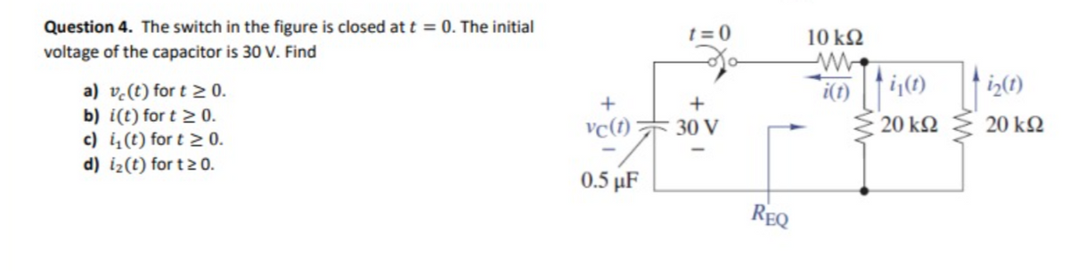
Question 4. The switch in the figure is closed at t = 0. The initial voltage of the capacitor is 30 V. Find a) ve (t) for t≥ 0. b) i(t) for t≥ 0. c) i(t) for t≥ 0. d) [₂(t) for t≥ 0. + vc(1) 0.5 µF t=0 30 V REQ 10 kQ2 i(t) i₁(t) 20 ΚΩ i₂(1) 20 ΚΩ


Q: Hilt 20V RI DI 12 RI RJ 0.5k Calculate the DC operating point of the circuit. The diodes have the…
A: Given Circuit:Diode parameters:Aim:To find the DC operating point of the circuit
Q: 3 Consider the following discrete-time Signalss X₁ [n] = {0, 1,2,3,4} X₂ [n] {011,01010} S[] = {…
A: Given signals:To determine:Y[n], such that X3[n] such that
Q: 2. Determine the inverse z transform of X(z) = = 1+ 2z¹+z-² 1 3 -1 Z + Z-2 2 Also plot the poles and…
A: The pole is point at which the denominator of system become zero. The zero is point at which the…
Q: 5-If V = (Last 2 digits of your student number) Sinat, what is V? -/20 Ω 20 Ω -j20 Ω 20 Ω
A: The circuit diagram,
Q: 4) Calculate the voltage Vx and the current through the coil in the circuit below. (For t=0, it is…
A:
Q: QUESTION 2 The switch in the circuit of figure 2 has been in position a for a long time. At t=0 the…
A:
Q: Solve for the current flowing through the 8 resistor in the following figure. 292 452 SV www isa 852…
A: I8ohm = ?
Q: In an RLC circuit, L = 0.1; H₁; R=0.6; 22,; C=0.4;F, and E(1) = 60; V. Find the charge at time 1.…
A: Given dataInitial charge, Initial current, To find outExpression for the charge
Q: (c) A 240 V DC shunt motor provides power to a load at 900 rpm. The current in the armature is 120…
A: Given dataTerminal voltage, Speed, Armature current, Armature resistance, Field resistance/shunt…
Q: Extend the data path implementation and the controller to process the Jalr instruction:…
A: Solution:Given data:=> opcode: 001001=> Operation: R[31] = PC + 4 ; PC = R[rs]Find :here we…
Q: Practice Problem 19.6 h₁ = 2 k h12=104 h21 = 100 h₂2 = 10-5 S Zin Figure 19.27 For Practice Prob.…
A: The h parameters,The load resistor, The port network,
Q: 1. The switch in the following circuit has been closed for a long time and it is opened at t= 0.…
A: The circuit diagram,
Q: Q-Select the correct answer: a- The time ts of a voltage commutated chopper is 2-2π√√LC, 3-0.5√/LmC,…
A: “Since you have posted a question with multiple sub parts, we will provide the solution only to the…
Q: A 200 KVA, single phase two-winding transformer rated 4160/ V, 60 Hz has primary and second…
A: We have to Answer the following questiona. The core loss at normal operation and the maximum and…
Q: 3. Find the all-day efficiency of 600 kVA distribution transformer whose Cu loss and iron loss at…
A:
Q: Find Idc, Vdc and the capacitance that will force the Vr(pp) to 3mV. Draw the output waveform across…
A: It is given that:
Q: In the circuit shown, the switch indicated is open for a very long time, and then closed at t=0.…
A:
Q: 18 V + 1.6 ΚΩ 5 ΚΩ Σ1 ΚΩ Rf •9V : 10.4 ΚΩ
A: We need to find out value of Rf to work op amp in saturation region.
Q: (6) 3.- A 6-pole, 440V and 60 Hz three-phase induction motor operates with a slip of 0.05 and has an…
A: Given dataPole, Supply voltage, Supply frequency, Slip, Output power, Stator copper loss, Rotational…
Q: Find the voltage between points a and b (in V). A. 3 B. -5 C. 6 D. 1 70 m 40 * 12V m 20 9V www 11₂
A:
Q: (1) a. Current voltage characteristic of a diode i = {kv², v>0 v<0 given in the form. What is the…
A:
Q: *7.18 The circuit in Figure P7.3 looks like a counter. What is the sequence that this circuit counts…
A: The sequential circuit,
Q: Switch S1 has been closed and S2 has open for a long time until the capacitors are fully charged. At…
A:
Q: Find the Norton current associated with this circuit (downward, in Amps) ww + I 2 Answer in Amps R1…
A: it is asked to find the norton current
Q: 1.) The core of a 50KVA, 2-winding is used for an autotransformer with a voltage rating of 360/120V.…
A: KVA rating of 2-winding transformer Voltage rating of transformer 360/120 V.
Q: what is the minimum soze internal bonding conductor for a 15 amp circuit breaker protecting device…
A: Given that a 15 amp circuit breaker protecting device mounted on the door. We have to find the…
Q: F(s) = 40 2 (s² + 4s+5)²
A:
Q: Solve for current I1, I2, ID1, and ID2
A: Given:A circuit, To find:The values of currents I1, ID1, I2, ID2.
Q: Switch S1 has been closed and S2 has open for a long time until the capacitors are fully charged. At…
A:
Q: Question 3: For the case of oblique incidence of a uniform plane wave with perpendicular…
A: Given an oblique incidence of a uniform plane wave with perpendicular polarisation on a boundary…
Q: 1 17. The series resistances of the high voltage and low voltage windings of a 50Hz, single phase…
A: The series resistances of the high voltage and low voltage windings of a 50Hz, single phase…
Q: (a) X(s) = (b) X(s) = 41.6667 S³+3.7444² +25.7604s+ 41.6667 S³ (s+5)(s² +5s+25)
A:
Q: 2. A sequential circuit with two D flip-flops A and B, two inputs X and Y, and one output Z is…
A:
Q: The values of the passive elements and the AC Voltage and Current sources which are shown on the…
A:
Q: Define the quantization error and then show how it is changing when using an A/D converter with…
A: When an analogue signal is converted to a digital signal by an analog-to-digital converter (ADC), a…
Q: A 40 kHz sinusoidal voltage has zero phase angle and a maximum amplitude of 25 mV. When this voltage…
A:
Q: Calculate the gains of the controller K(s) = Kp + that stabilizes the closed-loop system. Comment on…
A:
Q: Question 2: A uniform plane wave is travelling in the z direction in air with its magnetic field…
A: The uniform plane wave is travelling in z-direction in air with its magnetic field in y-direction.At…
Q: You want to design a synchronous counter sequential (sequential) logic circuit. It will count from 0…
A: Need to design a sequential circuit that need to count from 0 to 9 and it should not count 2. The…
Q: The z-parameters Z11, Z12, Z21, and z22 are measured in a. A/A b. V/V C. A/V d. V/A
A: Z - parameter.Z parameter of two port network is given by equation.
Q: 3.36 Find V, in the circuit in Fig. P3.36 using nodal analysis. σν -+ 12 ΚΩ 2 mA Figure P3.36 12 ΚΩ…
A: Vo=?
Q: Thevenin equivalent resistance
A:
Q: 20 V 502 www Ⓒ 2134A Ⓒ 0.0365 A O 00108 A Ⓒ 0.871 A O 0.147 A www 150 4 40 60 K Assume forward…
A:
Q: A) Calculate the DC output voltage and the emitter currents of Q1 and Q2. B) Sketch then the…
A: here
Q: 3. a) A signal x(t) = 3• (-¹) (over -3 ≤t ≤ 3) would have the shape of Choose one.__ (1) 3 e³ b)…
A: A function x(t),We have to plot the function,which has has been modified by using different time…
Q: 2. An 12,500/440 V, 250 kVA, single-phase, 60 Hz transformer has core loss of 2.2 kW and Cu loss of…
A:
Q: 1. Consider an LTI system with the following DE 1 1 y(n) — — y(n − 1) — {√y[n−2] = 0, with y[−1] =…
A:
Q: I can't view images
A: here we have to find the voltage V0 using thevenin theorem.
Q: You want to design a synchronous counter sequential (sequential) logic circuit. Counting from 0 to 9…
A: The sequential circuit needs to be designed and it has to count from 0 to 9 and it should not count…
Q: 3) Find the transfer function of the system given below R(S) + G₁ G₂ HA H₁ وٹو G3 G4 H3 H₂
A: Asked to find transfer function of the system?

Step by step
Solved in 3 steps with 3 images

- In the circuit of the figure, the switch S has been in position a for a long time; when the current through the inductor is maximum, the switch changes to position b (this instant is taken as t = 0). If the current source is iS(t) = 2.1213 cos (100πt + π/ 4). Determine: i) the value of R2 so that at t = 4 mS the current iL (t = 4mS) = 1 A. ii) The expression for the inductor current iL(t) t> 0 iii) the value of iL(t) at t = 0. iv) the expression of the inductor voltage vL(t) t> 0. v) the value of vL(0).1) The circuit shown below is initially, for t < 0, with capacitor C connected to a battery (Vbat = 12 V).The key is switched at t = 0, disconnecting the battery and turning on the capacitor to the rest of the circuit.a)Calculate the circuit current in the time domain, i(t).b) In practice, after how long can the energy stored in the circuit be considered to be irrelevant (close to zero)?The triangular voltage pulse shown below is applied to a 200 mF capacitor. a) Write the expressions thatdescribe vc(t) in the five time intervals t < 0, 0 ≤ t ≤ 2 , 2 ≤ t ≤ 6, 6 ≤ t ≤ 8, and t > 8. b) Derive theexpressions for the capacitor current, power, and energy for the time intervals in part (a).
- Given the circuit below with the switch closed for a long time, then opening at t=0, and with the values R1=193KΩ, R2=186KΩ, R3=107KΩ, calculate the capacitor voltage at t =0.Please answer ASAP and I'll upvote, thank you. In the given circuit, switch S1 is in position A and switch S2 is open. Both switches are in these states for a very long time. At t=0, switch S1 moves from position A to B while switch S2remains open. 10ms after switch S1 moves to position B, switch S2 is closed and remains closed for 20ms only. Determine the expressions for the inductor current for 0≤t<10ms, 10ms≤t<30ms, 30ms≤t<∞, and determine the time (in ms) after switch S1 moves to position B is the current in the inductor equivalent to 30% of the initial value (at ?=0).In the circuit shown, the switch is inthe closed position for a long timebefore it opens at time ? = 0.A. Find the differentialequation satisfied by the outputvoltage, v0(t) for t> 0. B. the initial conditions for this circuit are: v0(0+) = 0 and dv0/dt(0+) =−30,000 V/s. .findv0(t) for t > 0.
- An electric circuit contains a 1-H inductor, a 4-$ resistor, and a voltage source of sin t. The resulting differential equation relating the current i and the time t is di / dt + 4i = sin t. Find i after 0.5 s by Euler's method with At= 0.1 s if the initial current is zero. Solve the equation exactly and compare the values. Use Euler's method to find i after 0.5 s. iapprox = A Round the final answer to four decimal places as needed. Round all intermediate values to nine decimal places as needed.)The current in and the voltage across a 5 H inductor are known to be zero for t≤0. The voltage across the inductor is given by the graph shown for t≥0. 1. Derive the expression for the current as a function of time in the intervals 0≤t≤1 s, 1 s≤t≤3 s, 3 s≤t≤5 s, 5 s≤t≤6 s, and 6 s≤t<∞. 2. For t>0, what is the current in the inductor when the voltage is zero? 3. Sketch i versus t for 0≤t<∞.The two switches in the circuit shown in Figure operate synchronously. When switch 1 is in position a, switch 2 is closed. When switch 1 is in position b, switch 2 is open. Switch 1 has been in position a for a long period of time. At t = 0, it moves instantaneously to position b. Determine vc(t) for t ≥ 0.
- The circuit shown is at steady state before the switch closes. The inductor currents are both zero before the switch closes (i1(0) = i2(0) = 0). The voltage across the 2H-inductor is 4e-5t V for t > 0, otherwise 0V for t < 0. (a) Determine the inductor currents i1(t) and i2(t) for t ≥ 0. (b) Determine the energy stored by each inductor 200ms after the switch closes. (c) In the equivalent inductor (for the parallel inductors) determine the (i) current and the (ii) energy stored for 200 ms after the switch closes. Answer: 0.4(1 − e−5t) A, 0.1(1 − e−5t) A, 16.0mJ, 63.9mJ, 316mA, 79.9mJIn the circuit shown, the switch is open, and the capacitors are uncharged. At t=0, the switch S is closed. Find the equivalent resistance of the circuit at t=0. R1=2R, R2=R, C1=C, C2=2C.The current i(t) in an RL circuit is governed by the differential equation di/dt + R/L i = 1/L (E(t)), where R and L are constants and E(t) represents the applied EMF. At t = 0, the switch in the circuit isclosed, and the applied EMF increases linearly from 0 V to 10 V in a time interval of 5 seconds. The EMF thenremainsconstantfort ≥5.Determinethecurrent in the circuit for t ≥0.