11.7 Find the impedance, complex power, apparent power, average power, reactive power, and power factor of the load shown in Figure P11.7 when the magnitude of the voltage across the load is | Vrms | = 250 V and the radian frequency is w = 260 rad/s Figure P11.7 www R2 R₁ • 20 Ω Vims 60 Ω L 115 mH 9μF
11.7 Find the impedance, complex power, apparent power, average power, reactive power, and power factor of the load shown in Figure P11.7 when the magnitude of the voltage across the load is | Vrms | = 250 V and the radian frequency is w = 260 rad/s Figure P11.7 www R2 R₁ • 20 Ω Vims 60 Ω L 115 mH 9μF

Power System Analysis and Design (MindTap Course List)
6th Edition
ISBN:9781305632134
Author:J. Duncan Glover, Thomas Overbye, Mulukutla S. Sarma
Publisher:J. Duncan Glover, Thomas Overbye, Mulukutla S. Sarma
Chapter2: Fundamentals
Section: Chapter Questions
Problem 2.17P: Consider a load impedance of Z=jwL connected to a voltage and V let the current drawn be I. (a)...

Related questions
Question
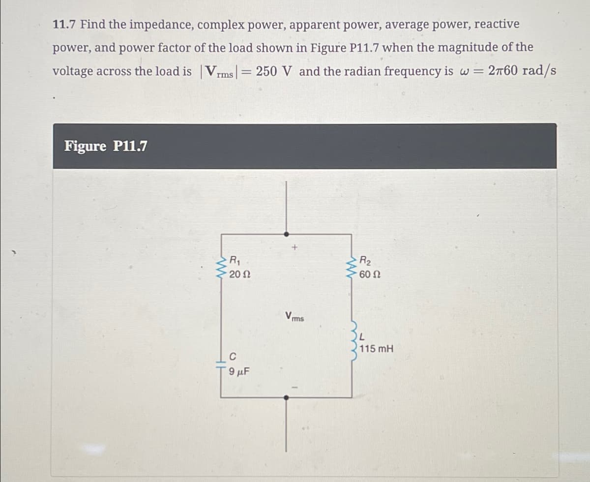
Transcribed Image Text:11.7 Find the impedance, complex power, apparent power, average power, reactive
power, and power factor of the load shown in Figure P11.7 when the magnitude of the
voltage across the load is | Vrms | = 250 V and the radian frequency is w = 260 rad/s
Figure P11.7
www
R2
R₁
• 20 Ω
Vims
60 Ω
L
115 mH
9μF
Expert Solution
This question has been solved!
Explore an expertly crafted, step-by-step solution for a thorough understanding of key concepts.

Step by step
Solved in 2 steps with 2 images

Recommended textbooks for you
Power System Analysis and Design (MindTap Course …
Electrical Engineering
ISBN:
9781305632134
Author:
J. Duncan Glover, Thomas Overbye, Mulukutla S. Sarma
Publisher:
Cengage Learning
Power System Analysis and Design (MindTap Course …
Electrical Engineering
ISBN:
9781305632134
Author:
J. Duncan Glover, Thomas Overbye, Mulukutla S. Sarma
Publisher:
Cengage Learning