12) Study the ladder logic program in the figure below and answer the questions that follow: a. What is the purpose of interconnecting the two timers? b. How much time must elapse before output PL is energized? c. What two conditions must be satisfied for timer T4:2 to start timing? d. Assume that output PL is on and power to the system is lost. When power is restored, what will the status of this output be? e. When input PB2 is on, what will happen? f. When input PB1 is on, how much accumulate. Ladder logic program Output PB2 L2 T4:1 Inputs (RES) L1 T4:2 PB1 (RES) PL PB2 -RTO PB1 RETENTIVE TIMER ON T4:1 EN 1.0 2900 CON) Timer Time base Preset Accumulated -RTO PB1 T4:1 RETENTIVE TIMER ON Timer Time base T4:2 (EN) 1.0 1780 DN Preset (Na) CON) Accumulated T4:2 PL HE DN
12) Study the ladder logic program in the figure below and answer the questions that follow: a. What is the purpose of interconnecting the two timers? b. How much time must elapse before output PL is energized? c. What two conditions must be satisfied for timer T4:2 to start timing? d. Assume that output PL is on and power to the system is lost. When power is restored, what will the status of this output be? e. When input PB2 is on, what will happen? f. When input PB1 is on, how much accumulate. Ladder logic program Output PB2 L2 T4:1 Inputs (RES) L1 T4:2 PB1 (RES) PL PB2 -RTO PB1 RETENTIVE TIMER ON T4:1 EN 1.0 2900 CON) Timer Time base Preset Accumulated -RTO PB1 T4:1 RETENTIVE TIMER ON Timer Time base T4:2 (EN) 1.0 1780 DN Preset (Na) CON) Accumulated T4:2 PL HE DN

Delmar's Standard Textbook Of Electricity
7th Edition
ISBN:9781337900348
Author:Stephen L. Herman
Publisher:Stephen L. Herman
Chapter13: Magnetic Induction
Section: Chapter Questions
Problem 1PA

Related questions
Question
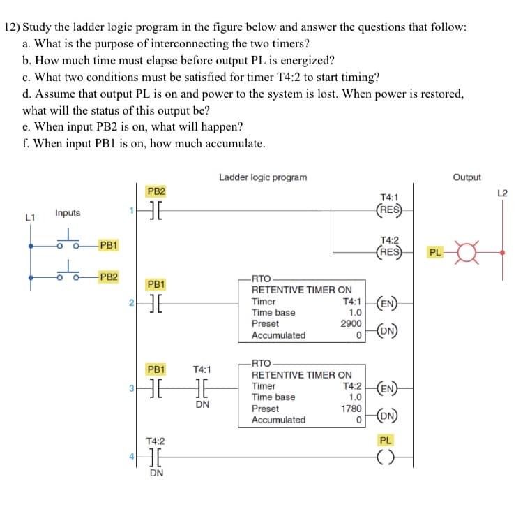
Transcribed Image Text:12) Study the ladder logic program in the figure below and answer the questions that follow:
a. What is the purpose of interconnecting the two timers?
b. How much time must elapse before output PL is energized?
c. What two conditions must be satisfied for timer T4:2 to start timing?
d. Assume that output PL is on and power to the system is lost. When power is restored,
what will the status of this output be?
e. When input PB2 is on, what will happen?
f. When input PB1 is on, how much accumulate.
Ladder logic program
Output
PB2
L2
T4:1
(RES
Inputs
L1
T4:2
(RES
PB1
PL
PB2
-RTO
PB1
RETENTIVE TIMER ON
T4:1 EN
1.0
2900
CON)
Timer
Time base
Preset
Accumulated
-RTO
PB1
T4:1
RETENTIVE TIMER ON
Timer
Time base
T4:2 (EN)
1.0
DN
Preset
1780
ON)
Accumulated
T4:2
PL
HE
DN
Expert Solution
This question has been solved!
Explore an expertly crafted, step-by-step solution for a thorough understanding of key concepts.

This is a popular solution!

Trending now
This is a popular solution!

Step by step
Solved in 2 steps with 2 images

Knowledge Booster


Learn more about
Need a deep-dive on the concept behind this application? Look no further. Learn more about this topic, electrical-engineering and related others by exploring similar questions and additional content below.Recommended textbooks for you
Delmar's Standard Textbook Of Electricity
Electrical Engineering
ISBN:
9781337900348
Author:
Stephen L. Herman
Publisher:
Cengage Learning

Delmar's Standard Textbook Of Electricity
Electrical Engineering
ISBN:
9781337900348
Author:
Stephen L. Herman
Publisher:
Cengage Learning