1)The sending-end current and receiving-end current in a given transmission line are not equal b. Transmission line inductance a. Transmission line resistance b. Transmission line inductance d. Transmission line voltage 2. The phase voltage is equal to the line-to-line voltage in a delta connected 3- T
1)The sending-end current and receiving-end current in a given transmission line are not equal b. Transmission line inductance a. Transmission line resistance b. Transmission line inductance d. Transmission line voltage 2. The phase voltage is equal to the line-to-line voltage in a delta connected 3- T

Power System Analysis and Design (MindTap Course List)
6th Edition
ISBN:9781305632134
Author:J. Duncan Glover, Thomas Overbye, Mulukutla S. Sarma
Publisher:J. Duncan Glover, Thomas Overbye, Mulukutla S. Sarma
Chapter2: Fundamentals
Section: Chapter Questions
Problem 2.52P: A balanced three-phase load is connected to a 4.16-kV, three-phase, fourwire, grounded-wye dedicated...

Related questions
Question
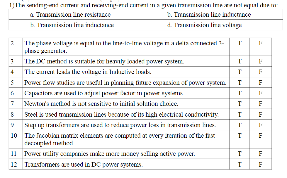
Transcribed Image Text:1)The sending-end current and receiving-end current in a given transmission line are not equal due to:
a. Transmission line resistance
b. Transmission line inductance
b. Transmission line inductance
d. Transmission line voltage
2
The phase voltage is equal to the line-to-line voltage in a delta connected 3-
F
phase generator.
3
The DC method is suitable for heavily loaded power system.
F
4
The current leads the voltage in Inductive loads.
T
F
5
Power flow studies are useful in planning future expansion of power system.
F
6
Capacitors are used to adjust power factor in power systems.
T
F
7
Newton's method is not sensitive to initial solution choice.
T
F
8
Steel is used transmission lines because of its high electrical conductivity.
T
F
9
Step up transformers are used to reduce power loss in transmission lines.
F
The Jacobian matrix elements are computed at every iteration of the fast
decoupled method.
Power utility companies make more money selling active power.
10
F
11
F
12
Transformers are used in DC power systems.
T
F
Expert Solution
This question has been solved!
Explore an expertly crafted, step-by-step solution for a thorough understanding of key concepts.

Step by step
Solved in 2 steps

Recommended textbooks for you
Power System Analysis and Design (MindTap Course …
Electrical Engineering
ISBN:
9781305632134
Author:
J. Duncan Glover, Thomas Overbye, Mulukutla S. Sarma
Publisher:
Cengage Learning
Power System Analysis and Design (MindTap Course …
Electrical Engineering
ISBN:
9781305632134
Author:
J. Duncan Glover, Thomas Overbye, Mulukutla S. Sarma
Publisher:
Cengage Learning