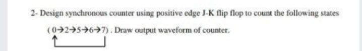
2- Design synchronous counter using positive edge J-K flip flop to count the following states (02 567). Draw output waveform of counter.


Q: Design a 2 bit binary down counter using SR flip flops.
A: 2 -bit binary down counter: The counting sequence is 3-2-1-0-3-2-1-0-....
Q: Design a 3 bits binary synchronous counter with JK flip-flops. That count the even numbers.
A:
Q: CIr CIk Next Output State FFs Dec Dec
A: To design a binary counter that counts from 0 to 5, we require three JK flip-flops. The clock of…
Q: 2- Design synchronous counter using positive edge J-K flip flop to count the following states…
A:
Q: The logic diagram of JK flip-flop is given in Figure 3. a) Write the output Boolean functions for…
A: A) Boolean function will be Q+ = JQ'+K'Q here Q+ is the next state
Q: Assume Flip flop is initially set to 01(Q1Q0) in the given counter circuit. Accordingly, determine…
A:
Q: Qi: Design a synchronous binary counter using D flip- flop with the sequence shown in the state…
A: In synchronous binary counters clock input clocked together at same time with the same clock input…
Q: 5. The waveform in Figure Q5 are applied to the inputs of a J-K flip-flops (negative-edge…
A:
Q: 1-The waveforms in the figure below are triggered D flip flop and a gated D latch (i.e., with enable…
A:
Q: Discussion: what is the effect the activating the (preset and clear) on the output state for J-K…
A: Preset and Clear are the two asynchronous inputs are provided to all flip-flops to make the output…
Q: Design 3-bits synchronous counter that count odd number using JK flip flops and any needed logic…
A:
Q: For the state diagram given below, create the state table and design the sequential circuit with SR…
A:
Q: Given a sequential circuit implemented using two JK flip-flop as in Figure Q.ba. Analyse the circuit…
A: Flip flop is a latch with additional control input (clock or enable ). In S-R flip flop when both…
Q: Design a 3 bits binary synchronous counter with JK flip-flops. That count from 0 to 7
A:
Q: Design synchronous counter(s) that go through each of the following sequence(s) f. 1 3 5 7 6 4 2 0…
A: The given sequence is: f. 1 3 5 7 6 4 2 0 and repeat
Q: Q6. For the following state graph, construct a transition table. Then, give the timing diagram for…
A: State diagrams are regularly used to represent the dynamic conduct of structures. The circles in a…
Q: Q5(a) Design a synchronous counter using JK flip-flop to obtain the following count sequence: 1, 4,…
A: A counter is a sequential circuit whose state represents the number of clock pulses fed to the…
Q: What is the type of the flip flop? Present state Next state output output At delay cross coupled D…
A: Based on the digital circuit
Q: Design synchronous 3-bit up counter with the following sequence 0, 1, 3, 4, 5, 7, 0 by using J-K…
A:
Q: a) write the characteristic table (Truth table) of SR flip flop b) draw logic diagram of SR flip…
A:
Q: Design a ripple counter using D flip flop to count from 4 to 8 and repeat.
A: Excitation table of D flip-flop is needed Present and next state are also available After all…
Q: 3 Consider a T flip-flop constructed from the negative edge triggered JK flip-flop with active low…
A: The solution is given below
Q: 1. Design a synchronous counter using JK Flip Flops where the binary equivalent states are changing…
A:
Q: Implement Logic clock divide by 2 and clock divide by 4 using minimum number of D flip flop.
A: Latch is asynchronous device. It is level triggered device. It check input and change output…
Q: Design a three bit synchronous binary counter that counts two by two with T-flipflops,
A: Here you have two draw a three bit synchronous counter by using two flip-flops A). first draw…
Q: 1- Design synchronous counter using negative edge D- type flip flop to count the following states:…
A:
Q: Discussion: what is the effect the activating the (preset and clear) on the output state for J-K…
A: a) Effect of activating the (present and clear) on the output state for J-K flip flop The…
Q: a) Build a falling edge triggered flip-flop circuit diagram
A: Faling edge triggered flip-flop circuit
Q: 26. Draw the logic diagram for a modulus-18 Juhnson counter. Show the timing diagram and write the…
A: A Johnson counter will produce a modulus of withnumber of stages or the flip-flops in the counter.…
Q: design NOR base SR flip flop and create table and ciruit and explain also
A:
Q: Digital Logic Design: Design 2,4,6,8,10 Up counter using jk flip flop with timing diagram.
A: Given components: JK Flip-flops To design: Up counter that counts- 2,4,6,8,10 Timing diagram
Q: Design asynchronous for the following sequence (0, 1, 2, 3, 4, 5, 6, 7, 8) counter and draw the…
A:
Q: Determine the Q output waveform of the flip flop in the Figure Q4(a). Figure Q4(a) Clock S Clock DC…
A:
Q: Design a 3 bits binary synchronous counter with JK flip-flops. That count from 0 to 4.
A:
Q: 1- Design synchronous counter using negative edge D- type flip flop to count the following states :…
A:
Q: Design synchronous counter using negative edge D- type flip flop to count the following states : ( 4…
A:
Q: / Design Synchronous counter using J-K flip flop to implement the following counting statements:…
A:
Q: Construct JK flip flop using D flip flop, 'multi plexer' and 'inverter'. I need conversion table and…
A: The digital circuits can be combinational and sequential circuits. The combinational circuits…
Q: 2-bit synchronous binary counter using T flip-flops
A: T flip flop- It is basically toggle flip flop. This flip flop is a modification of JK flip flop, in…
Q: asynchronous counters differs from a synchronous counter in * (a) the number of state in…
A: The digital circuits can be either combinational circuits or sequential circuits. Combinational…
Q: Do Qo Clock
A:
Q: Asm chart system given below in Hardwired hardware design structure with D flip flop design as.…
A: For the given algorithmic state machine, the state diagram can be drawn as follows:
Q: Q4/ design synch. Counter using T flip flop and any extra logic cct's needed to count the sequence…
A:
Q: For the ring counter in Figure 8–60, show the waveforms for each flip-flop output with respect to…
A: Fig: Given ring counter Although from above diagram it…
Q: Q5/ construct serial counter using PRE/CLR input flip flop that count in the following sequence…
A:
Q: Design synchronous counter using negative edge D- type flip flop to count the following states : (4…
A: "Since you have asked multiple questions, we will solve the first question for you. If you want any…
Q: Q2/Design mod-5 synchronous counter using JK flip flop. Note/use the steps of design of synchronous…
A:
Q: The following serial data stream is to be generated using a J – K positive edge – triggered Flip –…
A:
Q: 8. Design a synchronous counter, with module 11, NBC code using only T synchronous Flip Flops with…
A:

Step by step
Solved in 3 steps with 3 images

- Design a synchronous BCD Counter based on the following conditions. If last digit of your roll number is odd then design down-counter with JK-Flip Flops by initializing the counter with last digit and count next five states. The counter should cycle back after counting five states. Hint: roll number = 169Using JK Flip Flop, design a Synchronous counter that counts back and forth from 9 to 14, with arming signal at 11. a) Show the solutions, circuit and Karnaugh diagram. Please write nicely.how about if it's low level clocking d flip flop?? what is the waveform for it?
- Digital Logic Design: Design 2,4,6,8,10 Up counter using jk flip flop with timing diagram.Implementation of 8-bit Floating Light Digital Circuit Using JK Flip-Flopdesign it. (Hint: Using Shift Register)Construct a synchronous 3-bit Up/Down counter with irregular sequence by using J-K flip-flops. The state diagram is shown below.
- Design a 4-bit synchronous binary upcounter using T flip-flops. Draw only the logic diagram. Please show the process.Design a 3 bits binary synchronous counter with JK flip-flops. That count the odd numbersDesign a binary counter that counts from 0 to 5. At each clock pulse, 3 lights will be ON and 3 lights will be OFF. Use JK flip flops.Steps for solution:-> State diagram-> State table-> K-map reductions-> design
- Design a 2-bit synchronous binary counter using T flip-flops. Requirements: a.) State diagram b.) state table c.) State equation : A (t+1) = B (t+1) = d.) Flip-flop input functions : e.) Logic diagramDesign a synchronous 3-bit binary up-counter using D flip-flops.Determine the Number of FFs required, Counting Range, and Drow theexcitation table1)For the state diagram given below, create the state table and design the sequential circuit with SR type Flip Flop and draw the logic diagrams. Note: States A and B, input X, output Y