2. According to the network in Figure below, determine the amplifier parameter, input impedance, Zi, output impedance, Zo and voltage gain, Av. (7.01kn, 27.070, 0.98) Vcc = 20V 56 k2 B= 200 li 047 µF Vi 0.47 µF 8.2 k2 Vo 2 k2 Io 10 k2s
2. According to the network in Figure below, determine the amplifier parameter, input impedance, Zi, output impedance, Zo and voltage gain, Av. (7.01kn, 27.070, 0.98) Vcc = 20V 56 k2 B= 200 li 047 µF Vi 0.47 µF 8.2 k2 Vo 2 k2 Io 10 k2s

Power System Analysis and Design (MindTap Course List)
6th Edition
ISBN:9781305632134
Author:J. Duncan Glover, Thomas Overbye, Mulukutla S. Sarma
Publisher:J. Duncan Glover, Thomas Overbye, Mulukutla S. Sarma
Chapter12: Power System Controls
Section: Chapter Questions
Problem 12.3P

Related questions
Question
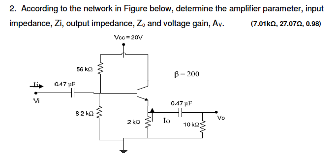
Transcribed Image Text:2. According to the network in Figure below, determine the amplifier parameter, input
impedance, Zi, output impedance, Zo and voltage gain, Av.
(7.01kn, 27.072, 0.98)
Vcc = 20V
56 k2
B= 200
li
047 µF
Vi
0.47 µF
8.2 k2
Vo
2 k2
Io
10 k2s
Expert Solution
This question has been solved!
Explore an expertly crafted, step-by-step solution for a thorough understanding of key concepts.

Step by step
Solved in 4 steps with 4 images

Knowledge Booster


Learn more about
Need a deep-dive on the concept behind this application? Look no further. Learn more about this topic, electrical-engineering and related others by exploring similar questions and additional content below.Recommended textbooks for you
Power System Analysis and Design (MindTap Course …
Electrical Engineering
ISBN:
9781305632134
Author:
J. Duncan Glover, Thomas Overbye, Mulukutla S. Sarma
Publisher:
Cengage Learning
Power System Analysis and Design (MindTap Course …
Electrical Engineering
ISBN:
9781305632134
Author:
J. Duncan Glover, Thomas Overbye, Mulukutla S. Sarma
Publisher:
Cengage Learning