2. Find the Norton equivalent (Draw the Circuit) with respect to terminal a and b in the circuit shown in the figure (Answer: IN = 1 A, RN = 10 ohms) 3 A 20 2 ww o a 180 V 40 2 12 Ω
2. Find the Norton equivalent (Draw the Circuit) with respect to terminal a and b in the circuit shown in the figure (Answer: IN = 1 A, RN = 10 ohms) 3 A 20 2 ww o a 180 V 40 2 12 Ω

Delmar's Standard Textbook Of Electricity
7th Edition
ISBN:9781337900348
Author:Stephen L. Herman
Publisher:Stephen L. Herman
Chapter22: Resistive-capacitive Parallel Circuits
Section: Chapter Questions
Problem 6RQ: Refer to the formulas in Appendix B in the Resistive-Capacitive Parallel Circuits section. A...

Related questions

Question
Norton equivalent
- please include its equivalent circuit diagram
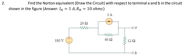
Transcribed Image Text:2.
Find the Norton equivalent (Draw the Circuit) with respect to terminal a and b in the circuit
shown in the figure (Answer: IN = 1 A, RN = 10 ohms)
3 A
20 2
ww
o a
180 V
40 2
12 Ω
Expert Solution
This question has been solved!
Explore an expertly crafted, step-by-step solution for a thorough understanding of key concepts.

This is a popular solution!

Trending now
This is a popular solution!

Step by step
Solved in 2 steps with 2 images

Knowledge Booster


Learn more about
Need a deep-dive on the concept behind this application? Look no further. Learn more about this topic, electrical-engineering and related others by exploring similar questions and additional content below.Recommended textbooks for you
Delmar's Standard Textbook Of Electricity
Electrical Engineering
ISBN:
9781337900348
Author:
Stephen L. Herman
Publisher:
Cengage Learning
Delmar's Standard Textbook Of Electricity
Electrical Engineering
ISBN:
9781337900348
Author:
Stephen L. Herman
Publisher:
Cengage Learning