Design a rectangular tied column for flexure in a reinforced concrete frame is subjected to the following loading scenarios: a. PD=200 kips, MD = 200 k-ft, PL = 100 kips, ML = 400 k-ft
Design a rectangular tied column for flexure in a reinforced concrete frame is subjected to the following loading scenarios: a. PD=200 kips, MD = 200 k-ft, PL = 100 kips, ML = 400 k-ft

Chapter2: Loads On Structures
Section: Chapter Questions
Problem 1P

Related questions

Question
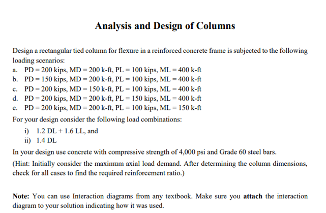
Transcribed Image Text:Analysis and Design of Columns
Design a rectangular tied column for flexure in a reinforced concrete frame is subjected to the following
loading scenarios:
a. PD = 200 kips, MD = 200 k-ft, PL = 100 kips, ML = 400 k-ft
b.
PD = 150 kips, MD = 200 k-ft, PL = 100 kips, ML = 400 k-ft
c. PD = 200 kips, MD = 150 k-ft, PL = 100 kips, ML = 400 k-ft
PD = 200 kips, MD = 200 k-ft, PL = 150 kips, ML = 400 k-ft
d.
e. PD = 200 kips, MD = 200 k-ft, PL = 100 kips, ML = 150 k-ft
For your design consider the following load combinations:
i) 1.2 DL + 1.6 LL, and
ii) 1.4 DL
In your design use concrete with compressive strength of 4,000 psi and Grade 60 steel bars.
(Hint: Initially consider the maximum axial load demand. After determining the column dimensions,
check for all cases to find the required reinforcement ratio.)
Note: You can use Interaction diagrams from any textbook. Make sure you attach the interaction
diagram to your solution indicating how it was used.
Expert Solution
This question has been solved!
Explore an expertly crafted, step-by-step solution for a thorough understanding of key concepts.

This is a popular solution!

Trending now
This is a popular solution!

Step by step
Solved in 5 steps with 2 images

Follow-up Questions
Read through expert solutions to related follow-up questions below.
Follow-up Question
How did you come up with the size of the rectangular cross section b = 16 inches and h = 24 inches in step 3 of this solution?
Solution
Follow-up Question
Does the solution for part a really end once the sketch for the tied column is drawn. Dont you have to check for the minimum width of the cross section?
Solution
Knowledge Booster


Learn more about
Need a deep-dive on the concept behind this application? Look no further. Learn more about this topic, civil-engineering and related others by exploring similar questions and additional content below.Recommended textbooks for you

Structural Analysis (10th Edition)
Civil Engineering
ISBN:
9780134610672
Author:
Russell C. Hibbeler
Publisher:
PEARSON

Principles of Foundation Engineering (MindTap Cou…
Civil Engineering
ISBN:
9781337705028
Author:
Braja M. Das, Nagaratnam Sivakugan
Publisher:
Cengage Learning
Structural Analysis (10th Edition)
Civil Engineering
ISBN:
9780134610672
Author:
Russell C. Hibbeler
Publisher:
PEARSON
Principles of Foundation Engineering (MindTap Cou…
Civil Engineering
ISBN:
9781337705028
Author:
Braja M. Das, Nagaratnam Sivakugan
Publisher:
Cengage Learning

Fundamentals of Structural Analysis
Civil Engineering
ISBN:
9780073398006
Author:
Kenneth M. Leet Emeritus, Chia-Ming Uang, Joel Lanning
Publisher:
McGraw-Hill Education


Traffic and Highway Engineering
Civil Engineering
ISBN:
9781305156241
Author:
Garber, Nicholas J.
Publisher:
Cengage Learning