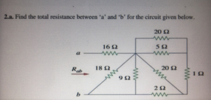
2.a. Find the total resistance between 'a' and 'b' for the circuit given below. 20 2 ww 50 162 ww 20 2 ww Rab 18 2 1 22 ww b. ww


Q: 4. A single-loop negative feedback system has the loop transfer equation: L(s) = Ge(s)G(s) = K(s +…
A: GIVEN: L(s)=Gc(s)G(s) =K(s+2)2(s(s2+1)(s+8)) FIND: (1) sketch…
Q: The logic circuit shown in the given fig.2 can be minimised to X Yo
A: A gate logic circuit is shown below. We have to minimize the gate logic circuit.
Q: Perform a 4-bit Boolean logic circuit. An LED should be activated only when two signals are high,…
A: Given that: LED will be activated when only two input signals are high. A table is shown. A Boolean…
Q: Minimize the logic function Y(A,B,C,D)= Em(0,1,2,3,5,7,8,9,11,14). Use Karnaugh map. Draw logic…
A: Given logic function has 4 inputs, A, B, C, and D YA,B,C,D=∑m0,1,2,3,5,7,8,9,11,14 We have to…
Q: 10Ω Μ 1502 γ n Ich 10Ω 15Ω 15Ω an 10Ω 42077 α bn b SOFT 420 Har C
A:
Q: An npn transistor
A:
Q: The plots in Figure B1a, below, show a carrier signal modulated by a binary data sequence. Identify…
A: Given question is under digital communications techniques For binary amplitude shift keying…
Q: rcuit with a resistance of 25 ohms, the current flowing through the circuit is which of the…
A: Given, V=100 VR = 25 OhmI =?
Q: For the following circuit, find the -3dB bandwidth in Hz if the unity gain frequency ft is 100,000…
A: Given circuit: Unity gain frequency, ft=100,000 Hz
Q: Calculate the radiation resistance of current element whose overall length is λ/50.
A: The overall length of a current element is given as le=λ50. The radiation resistance of the current…
Q: 3. Determine whether the systems with the following characteristic equations are stable or unstable:…
A:
Q: Use superposition theorem to find the value of VÀ in the following circuit due 3A
A: Given circuit diagram,
Q: A lossless TL with characteristic impedance of to is terminated in Zv=3Z0. use crank diagram to…
A: Since you have asked multiple questions, we will solve the first question for you. If you want any…
Q: A 3-phase induction motor draws 50 kW from a 220 V, 50 Hz mains. The rotor emf makes 100…
A: Given, A 3-phase induction motor draws, Electrical input = 50 kW Stator losses = 2 kW Supplied…
Q: Use superposition theorem to find the value of VÀ in the following circuit due 3A current source E…
A: Given circuit,
Q: (a) Calculate the synchronous speed of an eight-pole induction motor when supplied with power from a…
A: Given: An induction motor has following specifications, Number of poles, P=8 Frequency of source,…
Q: The voltage across a 1.1-kW toaster that produces a current of 10 A is: (a) 11 kV (b) 1100 V (c) 110…
A: Given, The power rating of toaster, P=1.1 kW Current rating, I=10 A
Q: A 16 kW, 480-V three phase two-pole 60-Hz induction motor has a slip of 0.025 when operating a…
A: Given, A three phase induction motor has following specifications Output power, P0=16 kW Rated…
Q: e 3,12. In the circuit shown in Fig. 3.12.1, the switch is moved mA to B at f-0. Find e(t) for t>0.…
A: Solution !!
Q: STA H⋅W. 1- Write the mesh equations, the find the current through R3 for the network R₁33-2 E₁ 15V…
A:
Q: Find the applied voltage on a forward biased diode if the current is 1mA and reverse saturation…
A:
Q: An apparatus that converts analog data into its digital equivalent is referred to as a digitizer.…
A: Given: Digitizer: Digitizer is an apparatus used to convert the analog data into digital data. It is…
Q: 25 MVA 13.8 kV generator with X"d=15% is connected through a transformer to a bus which supplies…
A: Fault currents that are symmetrical and asymmetrical. The system/synchronous machine's reactance is…
Q: The logic circuit shown in the given fig.2 can be minimised to
A: NOT gate- For input X- Output, Z=X' NOR gate with input X and Y- Output, Z= X+Y' =X'Y' NAND gate…
Q: What is the mass of an assembly of 1000 protons?
A: In this case, the mass of an assembly of 1000 protons is to be determined.
Q: In the circuit given below, C = C1 = C2. Find the gain of the multiple-feedback band-pass filter
A: The given circuit is According to the question Output of the circuit is given by C=Cin+Cout From…
Q: In a 66 KV system the phase is ground capacitance is 0.05 µF and inductance is 2H. The voltage (kV)…
A: Given a 66 kV system with, Capacitance, C=0.05 μF Inductance,k L=2 H Current that be interrupted,…
Q: Infinite uniform line charges of 5 nC/m lie along the (positive and negative) x and y axes in free…
A: Given: Charge per unit length, λx=λy=5nC/m Permittivity of the free space, εo=8.854×10⁻¹²F/m…
Q: A strain gauge of 100 2 is mounted on a steel cantilever beam at distance of 20 cm from free end. An…
A: We have an strain gauge with, Resistance of strain gauge (R) = 100 Ω Deflection of cantilever (y)…
Q: 3- Using D-Y or Y-A conversion, find the current I in the network R₁S. I 1/1K2 кл TOV E R₂2K R6 WW 2…
A: Using Delta to star or star to delta conversion calculation of current I for the given circuit. If…
Q: give a description of this wave form, from a non-synchronous buck converter. The wave form is from…
A: The signal waveform across the MOSFET is given as
Q: Example: Sketch the single-sided and double-sided spectra of x(t) = 2 sin (10nt - ²n)
A:
Q: Consider the circuit of figure below. The op- amp used is ideal. Determine I, and Vop if V₁ = 2 [V].…
A:
Q: 3 A conductor with a specific weight of 40.10 kg / m.mm2 was drawn with a tension of 10 kg/mm²…
A:
Q: Simplify the following expression into sum of products using Karnaugh map…
A: It is given that: FA,B,C,D=∑1,3,4,5,6,7,9,12,13
Q: Find the damping ratio and natural frequency for each second-order system shown below and show that…
A: Given data, Transfer function is given as, Ts=5s+3s+4=5s2+7s+12
Q: Where did the -0,4V come from??
A: In the given circuit, one of the requirements is to achieve maximum gain and it can be achieved by…
Q: Que 14 Sketch output voltage (V) for the network of Fig. 1.6.1 for the input given. Assume diodes…
A: It is given that:
Q: An 8-pole lap-connected armature has 40 slots with 12 conductors per slot generating a voltage of…
A: The voltage supplied to the motor by an external power source is known as EMF or electromotive…
Q: The phase shift oscillator circuit shown, is designed to oscillate at 155 [Hz]. Determine the value…
A: The phase shift oscillator circuit shown, is designed to oscillate at 155 [Hz]. Determine the value…
Q: = 4. ★★ Two coaxial air-filled solenoids, A and B, of equal length (€ = 20.0 cm) and radii R₁ = 2.50…
A:
Q: Calculate the reverse saturation current of a diode if the current at 0.2V forward bias is 0.1mA at…
A:
Q: Dynamic force microscopy experiments can be conducted by setting a feedback signal on the amplitude…
A: Dynamic force microscopy: It is a non-contact approach where through amplitude and frequency of a…
Q: What are the internal resistance and voltage rating of a 45 W an electric kettel that draws 3.7 A a.…
A: Given, An electric kettle is having Power rating, P=45 W Current drawn, I=3.7 A
Q: A closed loop system has the characteristic equation given by s³ + Ks² + (K + 2)s +3= 0. For this…
A: Given, A closed loop system has characteristics equation, s3+Ks2+K+2s+3=0
Q: Why is having a certain bandwidth so crucial?
A:
Q: An antenna having a radiation resistance of 7502 is radiating 10 kW. How much current flows into the…
A: Given information: The radiation resistance of the antenna is Rr=75 Ω and the power radiated by the…
Q: Design a unity gain inverting summing amplifier that will output the sum of two input voltages. Use…
A:
Q: In the following circuit, find the power dissipated (in Watts) in the resistance R. Take Is 12 A and…
A: Given data, is=12 A, R=4 Ω Circuit diagram is given as,
Q: An (open) electric circuit consists of an inductor, a resistor, and a capacitor. There is an initial…
A: Given that: Initial charge q(0)=2 C I=3 A E(t)=20 cos(t) The voltage drop across the resistor is 4…

Step by step
Solved in 5 steps with 5 images


- You are an electrician on the job. The electrical blueprint shows that eight 500-W lamps are to be installed on the same circuit. The circuit voltage is 277 V and is protected by a 20-A circuit breaker. A continuous-use circuit can be loaded to only 80% of its rating. Is a 20-A circuit large enough to carry this load?Using the following values for the circuit in the figure, find what is required in the questions? For the circuit in the figure, find the ones requested in the questions by using the following values? VT=2.99 V, ID(on)=5.54 mA, VGS(on)=5.3 V VG=? VGS Q =? ID Q =? VDS=?Since VDD = +15 V, VTH = +2 V and K = 100mA/V^2 in the circuit below, what is the ID current? (In circuit resistors The specified R value is in ohms) I want a quick solution, the method doesn't matter, the result matters
- Given the combination circuit, determine what is required below. a. What is the total resistance of the circuit? b. What is the total current of the circuit? c. What is the current in the 20-ohm resistor?For the circuit in the figure, find the ones requested in the questions by using the following values? VDD= 30 V, IDSS=8 mA, VP=-6V, R1=110 MΩ, R2=18 MΩ RD=1.9 kΩ, RS=3,68 kΩ VD=VS=VDS=Consider the following circuit and design the values (that is, decide the values) of the electrical elements (including the value of the constant k) so that VR1 = 6V and VR2 = 4V. The power dissipated by the resistive elements must not exceed 0.5 W.
- For the circuit in the figure, find the ones requested in the questions by using the following values? Vi= 26 V, VZ= 9,5 V, PZMAX=27,1 mW RS=2 kΩ RLmin=?RLmax=?For the given resistor combination circuit, determine (a) the equivalent resistance (show simplification of circuits), (b) the current demanded from the 15V voltage source (neglecting internal resistance), (c) the potential drop across each resistor, and (d) the current across each resistor.Calculate the maximum load resistance in ohms if E=10V, R=170 ohm, that will ensure that the voltage across the load resistance is 7V with a maximum Zener current of 8mA
- Draw a graph slowing the load line for the Thevenin circuit shown in Figure 1-26. On the same graph, show the IV curve for a 150kΩ resistor. Show the Q-input on your plot.I need to calculate VG,VS,VD,ID, and voltage out of the following circuit, the component is 2N5485 jFET, drain voltage of 25v and forward current of 10mAIn the circuit given in the figure | VBE | Since = 0.7V, R1 = 2.66Kohm, R2 = 11.73Kohm, RC = 0.79Kohm, RE = 2.36Kohm, VCC = 14.00V, Beta = 115.00, calculate the IC current by full analysis. When making your transactions, 2 steps will be taken after the point. Select the closest option according to +/- 10% margin of error. There is only one correct answer to the question.