바(2)w For the circuit in figure below, the lower critical frequency due to the output RC circuit (assumed re=D 9.6 Q and B = 150) is %3D Vcc +20 V Rc C3 2.2 kf2 R 33 k9 0.1 F R 5.6'k R, 0.1uF 50 9 Ry 4.7 k2 R 560 12 10F
바(2)w For the circuit in figure below, the lower critical frequency due to the output RC circuit (assumed re=D 9.6 Q and B = 150) is %3D Vcc +20 V Rc C3 2.2 kf2 R 33 k9 0.1 F R 5.6'k R, 0.1uF 50 9 Ry 4.7 k2 R 560 12 10F

Delmar's Standard Textbook Of Electricity
7th Edition
ISBN:9781337900348
Author:Stephen L. Herman
Publisher:Stephen L. Herman
Chapter24: Resistive-inductive-capacitive Parallel Circuits
Section: Chapter Questions
Problem 4RQ: A tank circuit contains a capacitor and an inductor that produce 30 of reactance at the resonant...

Related questions
Question
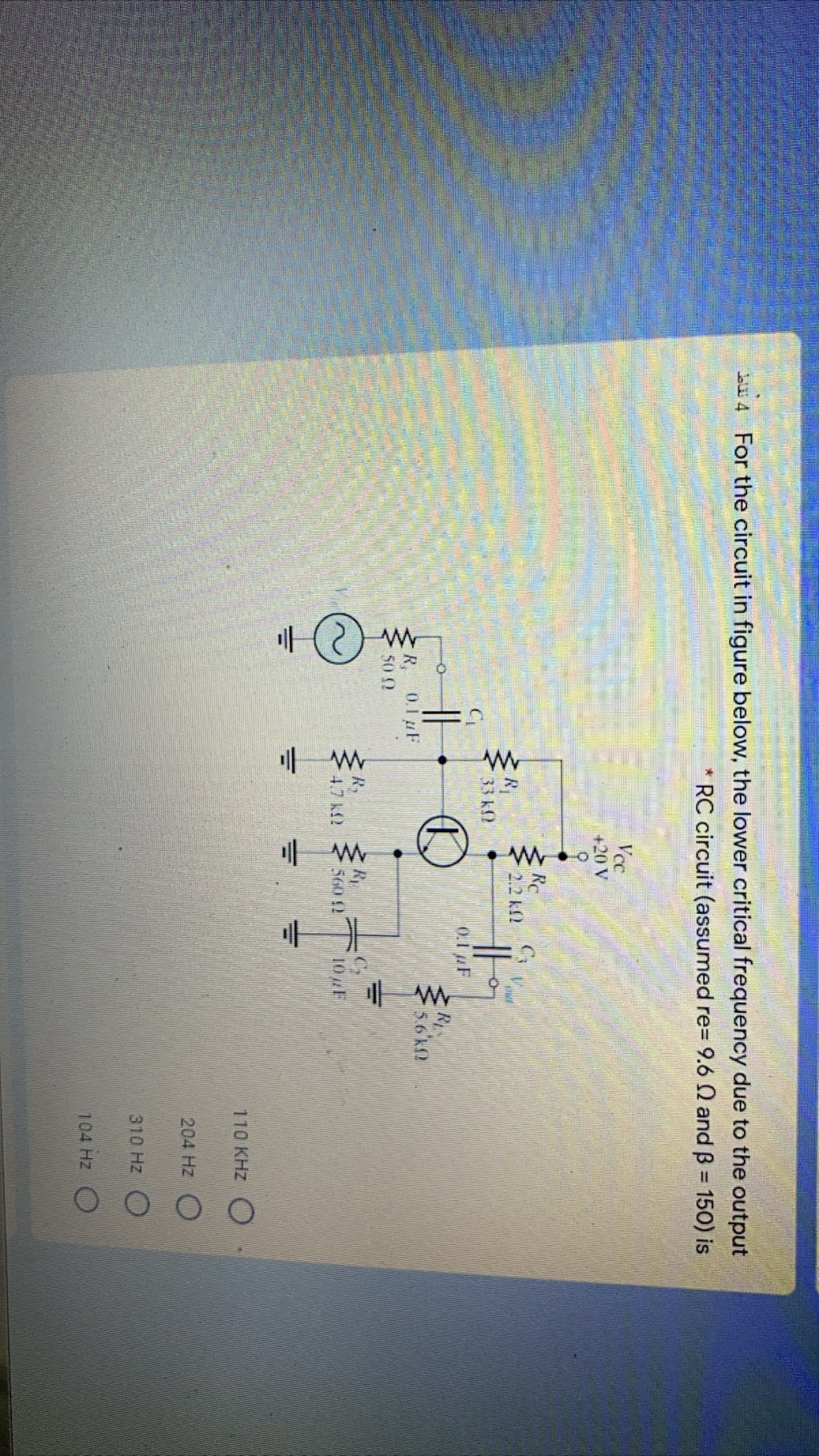
Transcribed Image Text:바(2)w
For the circuit in figure below, the lower critical frequency due to the output
RC circuit (assumed re=D 9.6 Q and B = 150) is
%3D
Vcc
+20 V
Rc
C3
2.2 kf2
R
33 k9
0.1 F
R
5.6'k
R, 0.1uF
50 9
Ry
4.7 k2
R
560 12
10F
Expert Solution
This question has been solved!
Explore an expertly crafted, step-by-step solution for a thorough understanding of key concepts.

Step by step
Solved in 2 steps with 1 images

Knowledge Booster


Learn more about
Need a deep-dive on the concept behind this application? Look no further. Learn more about this topic, electrical-engineering and related others by exploring similar questions and additional content below.Recommended textbooks for you
Delmar's Standard Textbook Of Electricity
Electrical Engineering
ISBN:
9781337900348
Author:
Stephen L. Herman
Publisher:
Cengage Learning
Delmar's Standard Textbook Of Electricity
Electrical Engineering
ISBN:
9781337900348
Author:
Stephen L. Herman
Publisher:
Cengage Learning