Q4. A series RLC circuit contains R = 20 N, L = 0.1 H and C = 0.1 µF. Calculate (a) resonant frequency (w,) (b) quality factor (Q) (c) bandwidth (B.W.) (d) half-power frequencies (w, and wz), (g) total impedance at resonance
Q4. A series RLC circuit contains R = 20 N, L = 0.1 H and C = 0.1 µF. Calculate (a) resonant frequency (w,) (b) quality factor (Q) (c) bandwidth (B.W.) (d) half-power frequencies (w, and wz), (g) total impedance at resonance

Delmar's Standard Textbook Of Electricity
7th Edition
ISBN:9781337900348
Author:Stephen L. Herman
Publisher:Stephen L. Herman
Chapter15: Alternating Current
Section: Chapter Questions
Problem 4RQ: 4. What is frequency?

Related questions
Question
Electrical Circuits_ Resonance
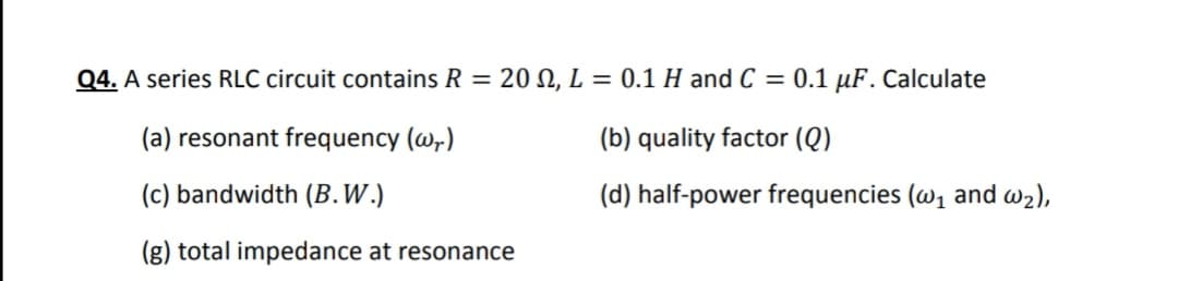
Transcribed Image Text:Q4. A series RLC circuit contains R = 20 , L = 0.1 H and C = 0.1 µF. Calculate
(a) resonant frequency (@,)
(b) quality factor (Q)
(c) bandwidth (B.W.)
(d) half-power frequencies (w1 and w2),
(g) total impedance at resonance
Expert Solution
This question has been solved!
Explore an expertly crafted, step-by-step solution for a thorough understanding of key concepts.

Step by step
Solved in 3 steps with 3 images

Recommended textbooks for you
Delmar's Standard Textbook Of Electricity
Electrical Engineering
ISBN:
9781337900348
Author:
Stephen L. Herman
Publisher:
Cengage Learning
Delmar's Standard Textbook Of Electricity
Electrical Engineering
ISBN:
9781337900348
Author:
Stephen L. Herman
Publisher:
Cengage Learning