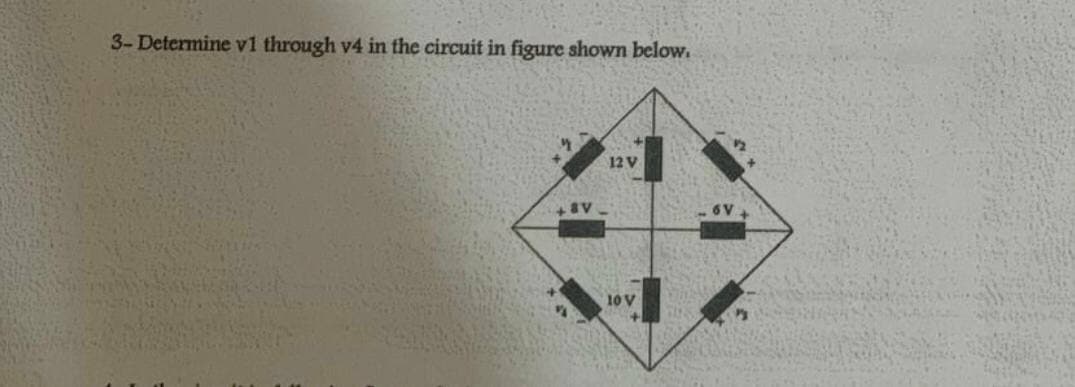
3-Determine v1 through v4 in the circuit in figure shown below. 12 V 10 V


Q: For the circuit below, solve for the current at 4-N resistor using Superposition Theorem -www- lo V
A: We have to find the current across 4ohm resistor using superposition
Q: For the circuit shown in the Figure below, use superposition to find “v" in terms of R's and source…
A: According to the question we have to find the value of v.
Q: For the following circuit, find V1, V2, and v3. 14 2
A: The solution can be achieved as follows.
Q: 42 15V R 4. 20V
A:
Q: Consider the given circuit where V = 13 V. Find Vo in the given circuit using superposition.…
A: Given circuit, And, V= 13 volt As in superposition theorem the response in any element is the sum…
Q: HW2 HW2: Apply Thevenin's theorem to find vo in the circuit of Figure below
A: Thevenin theorem states that any linear network with multiple number of sources and multiple…
Q: Find Vx, VBF, and VÅB in the network in Figure shown below. 4 V D
A:
Q: 6. Using superposition, find the current through R₁ in the circuit above.
A: The superposition theorem state that the response across any element is equal to the algebraic sum…
Q: 4- In the circuit in following figure, obtain y1, v2, and v3. 15 V 25 V 10 V 20 V
A: Kirchhoff's voltage law states that in a closed loop the sum of potential difference across an…
Q: HW//1- For the circuit shown below, find the value V1 ,and V2. +30V- -50 V+ 40 V
A: 1) To determine the values of V1 and V2 in the given circuit
Q: Refer to the given circuit below. Using Superposition Theorem, determine the percent contribution of…
A: In this question, We need to determine the percentage of the contribution of E2 to the current…
Q: In the case of the circuit in the figure, use nodal analysis to determine the value of v2 that will…
A:
Q: In the circuit given below find the voltage v, using superposition, that is by fimding the…
A: The superposition theorem states that a circuit with multiple voltage and current sources is equal…
Q: of figure below. Using the principle of superposition, determine the power dissipated in the 4-…
A:
Q: Consider the given circuit where V = 7 V. Find Vo in the given circuit using superposition.…
A: The given circuit is as shown below :
Q: Find the Thevenin's equivalent circuit for the network in the figure below
A: Thevenin theorem states that any linear network with multiple number of sources and multiple…
Q: For the circuit shown, A) Ri is in series with R2 B) R4 is in parallel with R1 C) R2 is in parallel…
A: (A) is not correct because R1is not in series with R2 .( Since current through R1 and R2 are not…
Q: (a) Relate v, in the circuit below to v1 ,V2 , and v3 .
A:
Q: 102 8V 22. Is
A:
Q: What happens when we encounter a circuit that has all 3 components in series? Parallel?
A: To answer above question, one should know basic circuit theory rules: Ohm's law: Ohm's law state…
Q: Find the value of v in the circuit shown in figure below.
A:
Q: If we would like to use Superposition to solve for Vo in the circuit shown above, we must find the…
A: The superposition theorem is sum of individual response of sources acting alone. The response due to…
Q: In the circuit given below, R = 8 Ω. Find the current i. The value of i in the circuit is ______…
A: Apply nodal analysis at V1V1-302+V13+V1-V26 = -4V112+13+16-V26= 15-4V112+36-V26 = 11V1 -V26 = 11 →…
Q: For the circuit in figure below, the value of Vx is: * R3 120 R2 120 + vx R1 V1 V2 12 v R4 60 60 12…
A:
Q: Q/ Using Mesh analysis to find the mesh currents for the circuit in figure below. 2 is
A: The solution can be achieved as follows.
Q: HW//1- For the circuit shown below, find the value V1 ,and V2. + 30 V - - 50 V + + 20 V - + - 40 V
A:
Q: Use mesh equations to find V in the circuits in Figure below. 6 V 4 kf 32 k! 2 kf? 6 kf 3 V ww
A: We will apply KVL in two loops , we will get mesh currents. Using ohms law we will find Voltage…
Q: NOTE: Solve this as soon as possible, I need this urgently. Determine the voltage Vpa in the circuit…
A: The given circuit is:
Q: Find /and Vab in the circuit given below, where the value of Vy is 70 V. 10 V 3Ω +) V, (+ Vab +)8 V…
A: To find the value of current I and Voltage Vab in the circuit
Q: Refer to the circuit below. The Thevenin resistance seen by the 20 V source is given by: 82
A: To find the thevenin;s resistance, short circuit the voltage source and open circuit the current…
Q: For the circuit shown in the Figure below, use superposition to find “v" in terms of R's and source…
A: This question belongs to circuit theory . It is based on the concept of super position theorem . In…
Q: Determine the node voltages in the figure below.
A:
Q: 4- In the circuit in following figure, obtain v1, v2, and v3. 15 V 25 V 10 V + '2 20 V
A: 4) The obtain V1, V2, V3 is as follows:
Q: V=Ei, R R2 R3 R. E
A: The detailed solution is attached with.
Q: a) The number of Reference node in the circuit is--------------- and the number of Non-…
A:
Q: Write equations for the circuit in the figure using generalized node voltage method. Vo R3 R2 1:n R1…
A: Given circuit shown
Q: Sum (superposition) theorem of current passing through resistance R2 in the circuit in the figure…
A: The superposition theorem states that a circuit with multiple voltage and current sources is equal…
Q: Using Superposition Theorem,
A:
Q: Use mesh equations to find V, in the circuits in Figure below. a) 2 k
A: NOTE: "Sine you have asked a question with multiple question, we will solve for first question for…
Q: Ехample: Find the voltage Vo in the circuit in Figure below
A:
Q: Given the circuit in the following figure, obtain the Norton equivalent as viewed from the following…
A:
Q: Use node voltage analysis to find the power of the dependent voltage source in the circuit shown…
A:
Q: Using loop analysis, find the four voltages V1, V2, V3 and V4 for the circuit below: 12 R7 500…
A: KVL states that total voltage drop across a loop is zero. It is based on the conservation of energy.…
Q: Q2 – For the circuit shown in the Figure below, use superposition to find “v" in terms of R’s and…
A: Solution:- Using superposition theorem, case 1, V2 : short circuit…
Q: The circuit shown in the figure below is a balanced bridge. B 1002 www 502 www A ER www 102 D Е.…
A: Bridge is balanced when product of opposite branches are same. AB,CD and BC, AD are the Opposite…
Q: Using Thevenin's theorem, find vo in the circuit given in the figure.
A: The thevenin's equivalent circuit can be obtained by using nodal analysis of the given circuit.
Q: s] For the circuit shown below, determine the values of the voltages Vx and Vo; and currents ii, i2,…
A:
Q: Apply Thevenin's theorem to find v, in the circuit of Figure below
A: Thevenin theorem states that any linear network with multiple number of sources and multiple…
Q: Example: For the circuit in Figure below, use the superposition theorem to find the current I, .
A: According to question: Case1) When only 12V is active. The current Io1 when only 12V is active in…
Q: Q2 – For the circuit shown in the Figure below, use superposition to find “v" in terms of R's and…
A: The problem related to circuit theory . It is related to super position theorem. Super position…


Trending now
This is a popular solution!

Step by step
Solved in 2 steps with 2 images


- Use the Principle of Superposition to determine the absolute value of total current, in milliamperes, through R1 in the circuit belowSolve and show solutions. (Circuit Diagram Image below)Solve Vce and Vbc on the circuit given below. Note that Vbe=0.7 V, Ve= 2V and Ic = Ie. 3 decimal places and complete solution please.
- Subject: Circuit INote:Support the problems with circuit diagram and label the pertinent partsWith full solutions pleaseSketch the DC equivalent circuit Determine IDQ and VDSQ Determine VD and VS Show the details of your work Thanks!Need help with this Question The D-MOSFET circuit shown in Figure Q1(b) has IDSS = 3 mA and VGS(off) =−8 V. Given the following:R1 = 50 kΩR2 = 150 kΩRD = 1 kΩRS = 2 kΩVDD = +10 VVSS = −10 VDetermine VGS, ID and VDS.
- In the circuit given in the figure VT = 25mV, | VBE | = 0.7V, R1 = 515.22Kohm, R2 = 10.89Kohm, R3 = 2.41Kohm, R4 = 1.03Kohm, VCC = 12.00V, VEE = 2.00V, VA = 12.51V, Beta Since = 107.00, Rs = 23.19ohm, Ry = 8.18Kohm, calculate the IC current, Ri, R0 and voltage gain according to the Source (V0 / V1) by making full analysis.Using superposition, with the 12V independent voltage source (IVS) acting alone, v0''' = ?A 620-V source connected to a resistor network described by RT = 50 + (R || 20) provides 120 V to the 20-ohm resistor. What is R?
- Consider the circuit diagram below. The circuit supplies power to the unknownresistive load, L. Determine the Thevenin equivalent circuit for the supply circuit.Verify that your Thevenin equivalent is indeed equivalent to the original circuitby simulating both circuits using CircuitJS and reporting the load current in each.Attach an exported image or screen shot of both of your circuits from CircuitJSwith the current and voltage “shown” (colors are shown on the diagram).In the node-voltage method, when a dependent voltage source connects two essential nodes, how can this situation be handled? A. The dependent source and its two ends are treated as a supernode for which a single KCL equation can be written. B. The two essential nodes are temporarily treated as having the same voltage. C. The dependent source is temporarily treated as an open circuit. D. The KCL equation is written for only one of the two essential nodes, and a KCL equation is written for the reference node. E. None of the provided options.Suppose you are planning to go on a country-side tour riding your bike. In an unfortunate situation, you find the bike battery drained and currently you don’t have access to any spare battery or workshop. The only power source you have access to is the AC supply of 120V (rms) at 50 Hz. You check the battery and it’s clear from the description level that the battery requires 12V DC source to charge up. Moreover, you are well aware that the socket mounted to your available AC source gives spike that’s sometimes provide higher value than the rated one. To solve this problem, you plan to build a diode-based circuit to obtain a continuous and fixed voltage output as well as solve the instability problem of the source. Criteria: 1. Consider regular diodes, Zener diodes, resistor, and capacitor as your available components. However, the only available diodes here are Ge based and Si based. 2. You must choose a diode with PIV rating higher than the peak value of AC input. 3. Your…