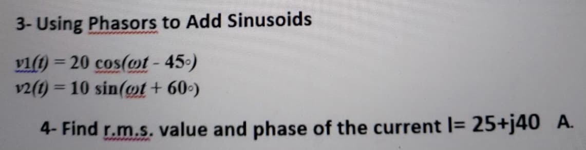
3- Using Phasors to Add Sinusoids vi(t) = 20 cos(ot-45) v2(1) = 10 sin(ot+ 60-) %3D


Q: For the ac network of Figure Q5, calculate the following; i. The total impedance; ii. The inductance…
A:
Q: Q 4) Obtain the sinusoids corresponding to each of the following phasors (a) V = 60/15° V, w = 1 %3D…
A: a)V1=60∠15° ; ω=1 rad/secV1t=V1sinωt+ϕV1(t)=60sin(t+15°) Volt
Q: A circuit has a resistance of 12 Q and capacitive reactance of 16 Q in series, If the applied…
A:
Q: #1. A series RLC circuit containing a resistance of 150, an inductance of 0.12H| capacitor of 470uF…
A: We are authorized to answer three subparts at a time, since you have not mentioned which part you…
Q: An inductive impedance of 32 ohm resistance and unknown inductance and a pure capacitor of 33.4…
A: In this question we need to find a value of unknown Inductance.
Q: 18/1.A. Draw the phasor diagram, also write the voltage and current relation statements for the…
A: Since it is an ac circuit the voltage and current will have phase angle between them. We will…
Q: Short Problem: Given a parallel RLC circuit comprised of the following element: 94.42-ohm resistor,…
A:
Q: Q-3 For the following pairs of voltages and currents, indicate whether the element involved is a…
A: Step 1 :- Find out total impedance. Step 2 :- Check impedance angle If, impedance angle is 0° then…
Q: Use a phasor diagram for the circuit to find the value of R thatcauses the current through that…
A: The current iR through the capacitor is in phase with voltage vm . The current iL through an…
Q: The circuit has a load consisting of the parallel combination ofthe resistor and inductor. Use…
A: Draw the circuit diagram without the capacitor.
Q: Question No. 4: For the below circuit, assume that: Vi(t) = 20 cos(wt+30°) V2(t) = 10 sin(wt+60°)…
A:
Q: Short Problem: Given a parallel RLC circuit comprised of the following element: 57.81-ohm resistor,…
A:
Q: Question No. 4: For the below circuit, assume that: V:(t) = 20 sin(wt+30°) V2(t) = 10 cos(wt+30°)…
A: In this question, Voltage equations are given. Write the phasor representation of the given…
Q: A series connection of a 30-ohm resistor and a 100-mH inductor is connected across 240-V, 60-Hz…
A: To find current equation from the given option
Q: A coil of resistance 152 and an inductance 1H and a capacitance 15µF are connected in series across…
A:
Q: Given a parallel RLC circuit comprised of the following element: 99.3-ohm resistor, ideal inductor…
A: In this question we need calculate true power .
Q: 1. A capacitor of 50 µF capacitance is connected in parallel with a reactor of 22 2resistance and…
A:
Q: Discussion 1- Explain why the phasor and the impedance have the same angle. 2- Compare the result…
A: To explain why the phasor and the impedance have the same angle
Q: Short Problem: Given a parallel RLc circuit comprised of the following element 62.96-ohm resistor,…
A:
Q: A coil of inductance 1 henry and negligible resistance is connected in series with a capacitance of…
A:
Q: Q-3 For the following pairs of voltages and currents, indicate whether the element involved is a…
A: In the question, Find the element of the given voltage and current equation. We are solving this…
Q: A coil of 50-ohm resistance and of 150-mH inductance is connected in parallel with a 50-µF…
A: From the given inductance and capacitance calculate inductive resistance and capacitive reactance.…
Q: 9. A 472 resistor, 30mH inductor and 60µF capacitor are connected in series across a 208V, 60HZ…
A:
Q: capacitor has 3. The been added to the load in the circuit shown in figure below to maximize the…
A:
Q: Given a parallel RLC circuit comprised of the following element: 63.92-ohm resistor, ideal inductor…
A:
Q: + 22 c=vc(t) C:
A: Since we are free to choose the capacitor value, let we choose capacitance value to be 10uF. At t=0,…
Q: If a phasor representation of a current is given by I = 70.7 ∠45° A, it is equivalent to
A:
Q: Find the phasors for the voltage and the currents of the circuit shown in the Figure. Construct a…
A:
Q: Solve for Rc of Figure 42. 12 V - Vc = 6V www Ra www Rc VCE B=80 IB = 40 μA Reference: Boylestad, R.…
A: Given the value of β=80 Consider the value of the collector voltage. Vc=Vce=6 V
Q: Short Problem: Given a parallel RLC circuit comprised of the following element: 62.52-ohm resistor,…
A: True power will be power dissipated in resistor . So we will find out current for resistor then we…
Q: the circuit impedance, (b) the circuit current, (c) the circuit phase angle
A:
Q: Conductance is always expressed as a imaginary number and comprised the imaginary part of admittance…
A: admittance = conductance + j susceptance . and admittance is the ratio of current to voltage .
Q: An AC circuit contains a 24-Ω resistor, a 15.9-mH inductor, and a 13.3-µF capacitor connected in…
A:
Q: Using your knowledge of the concept of expressing sinusoids in terms of
A:
Q: Summary: MCA in AC The circuit shown in Figure 2 is powered by three sources: ISI = 80 cos (80r) V…
A:
Q: Find phasous for the following expressions. a) v(t) = 21 cos(4t – 15°) V b) i(f) = –8 sen(10t + 70°)…
A: We are authorized to answer three subparts at a time, since you have not mentioned which part you…
Q: V₁ V₂ 2. For the dual oscilloscope displays shown in the figure with H, of 100 µs/div and V of 2…
A: Given in question: Hs=100 μs/divand Vs=2Vdiv (a): Frequency=1T For Waveform V1 : f1=1(3.2…
Q: An AC circuit contains a 24-Ω resistor, a 15.9-mH inductor, and a 13.3-µF capacitor connected in…
A: R , L and C are connected in parallel hence voltage will be same across each VR=240 VVL=240 VVc=240…
Q: 4. If voltage and current waveforms of the circuit given in the figure are v = 120 sin(314t) and i =…
A:
Q: A capacitor of 3.18 microfarads is connected in parallel with a resistance of 2,000 ohms. The…
A:
Q: XSC1 Fcn Gen C1 RS L1 Ext Trig 50Ω 15mH 0.033µF R1 V1 5100 Fig 3: Inductor, Capacitor, and Resistor…
A: V (t) = 3 sin(2π*5000t+0) Phasor form V = 3<0 ° L1 = 15mH C1 = 0.033 uf
Q: A 30-ohm resistor and a 0.1 H inductor are in series with a voltage source that produces a voltage…
A:
Q: 4. If voltage and current waveforms of the circuit given in the figure are v = 120 sin(314t) and i =…
A: Given: An AC supply v(t)=Vmsinωt is fed to a series RC circuit given as:…
Q: A capacitor of 3.18 microfarads is connected in parallel with a resistance of 2000 ohms. The…
A:
Q: A circuit consists of an inductance of 0.05 henry, a resistance of 5 ohms, and a condenser of…
A: Resistors, inductors and capacitors form an integral part of any electrical circuit. A source,…
Q: In the circuit shown in Figure 1, the source is Vi=10 sin(@t) V where @=2n × 200 rad/s. If the…
A:
Q: V₂ 3. For the dual oscilloscope displays shown in the figure with H, of 500 µs/div and V of 20…
A: As per the guidelines of bartleyby I need to answer first three subparts only so kindly repost other…
Q: 3. For the dual oscilloscope displays shown in the figure with H, of 500 µs/div and V, of 20 mV/div…
A:
Q: R = 3 N v.(t) = 325 cos 300t V C = 400 µF IL VL L = 2 mH Figure Q1 By referring to Figure Q1, answer…
A: Given: Circuit elements are known Supply voltage is given Calculate: voltage, current, impedance in…

Step by step
Solved in 2 steps with 3 images


- Suppose that v1(t)=100 cos(ωt) and v2(t)=100 sin(ωt). Use phasors to reduce the sum vs(t) = v1(t) + v2(t) to a single term of the form Vm cos(ωt+θ). Draw a phasor diagram, showing V1, V2 and Vs .State the phase relationships between each pair of these phasors.A series circuit of RLC with following parameters, R=15 ohm, L=20 m H & C=100 micro Farad. VT=169.7 sin (337t-30) Volt. Find the following: Zt, , It, Voltage across each element, Power factor, apparent power, real or average power and reactive power and the total phasor diagram and power phasor diagram(a) Calculate the equivalent impedance of the circuit given below, if the source voltage is v(t) = 60cos1000t (b) Calculate the source current flowing in the circuit (c) Draw the phasor diagram of the current and input voltage
- If the phasor voltage across an element is given by V=100∠120∘ and the phasor current through the same element is given by I=50∠30∘, which of the following basic circuit elements best represents this element? a. Insufficient information is given. b. Capacitor c. Some combination of these basic elements d. Resistor e. InductorTwo alternating voltages are given by v1 = 15sinωt volts and v2 = 25 sin (ωt – π/6) volts. Plot both functions on the same axes and hence determine a sinusoidal expression for the resultant vr = v1 + v2. Check your answer using an analytical method. Your manager has asked you to analyse the variation in in results between the two methodsConsider the current i(t)= 30sin(100t+90o) mA. is applied the circuit given below. a) Find and draw phasor equivalent of the circuit b) Find Iload and Vload phasors and and draw them on the real-imaginary axis. Find iload(t) and vload(t) via inverse phasor, comment phase angles c)Find active, reactive and complex power (P,Q,S) absorbed by the load. please fast
- QI Consider the circuit of Figure (1) z )0+ j40 Q Figl a. Calculate the sinusoidal voltages v1 and v2 using phasors and the voltage divider rule. b, Sketch the phasor diagram showing E, V1, and V2i (t) 40 2 cost A2 i (t) 30 2 cos(t 90) A2. Suppose thatFind i1 + i2。 3. A voltage source V is applied to a 100 μF capacitor.(1)Find the impedance of the capacitor.(2)Find the phasor current and phasor voltage.(3)Draw the phasor diagram.100cos200ut 4. Are the circuit voltages and impedancesgiven in the following diagrams correct?Z 7Ω U=14V ? Z 10Ω U=70V ?(a)34V1V26V8V+_U 6830V40V(b) 5. Are the circuit currents and impedancesgiven in the following diagrams correct?Z 2Ω I=8A ? Z 2Ω I=8A ?(c)4A4 4A4 A2IA1(d)4A4 4A4 A Z1 = (3+j4) Ω, Z2 = (8–j6) Ω, U 2200 V1 2 Find I , I , I .Z1 Z2 U+–I1 I 2 I,Using your knowledge of the concept of expressing sinusoids in terms of phasors in alternating current (ac) demonstrate how you will obtain the voltages v and V, the phasor current I and sketch phasor diagram if a circuit has a series combination of R=40Ω and L=80 mH and has a current i=2.0 Cos(500t+10o) (A)
- Find the phase relation for the following pairs of sinusoids, (which leads and lags which by how much). Draw the phasor diagram e1= -20sqrt2 sin(377t + 200°) V e2 = -10sqrt2 sin(377t - 285°) VConsider the voltage v(t)= 40sin(100πt+140 o ) V. a) Find the period of this voltage in millisecond and the voltage value at t=6 ms. b) This voltage is applied to the circuit below. Find VR , VC and VL phasors and and draw them on the realimaginary axis. Find vR(t) , vC(t) and vL(t) via inverse phasor, comment phase angles. c) Find active, reactive and complex power (P,Q,S) on the inductor.Three branches having impedances of 3+j4 Ω, 16−j12 Ω, and−j4 Ω, respectively, are connected in parallel. What are the equivalent(a) admittance, (b) conductance, and (c) susceptance of the parallelconnection in millisiemens? (d) If the parallel branches are excited froma sinusoidal current source where i=8 cosωt A, what is the maximumamplitude of the current in the purely capacitive branch?