3. A BME student designed a QRS detector for a heart rate monitor. The detector supposed to have a band-pass filter characteristic with central frequency 30 Hz, bandwidth 30 Hz (± 15 Hz around the center frequency) and gain of 100 at 30 Hz. He designed the filter and found out that the impulse response h(t) = 100e¬40t cos(180t + 12.5°). a. Find the transfer function of the filter. b. Determine the natural resonance frequency (on) and damping coefficient (5) of the filter. Draw the frequency response of the filter. C.
3. A BME student designed a QRS detector for a heart rate monitor. The detector supposed to have a band-pass filter characteristic with central frequency 30 Hz, bandwidth 30 Hz (± 15 Hz around the center frequency) and gain of 100 at 30 Hz. He designed the filter and found out that the impulse response h(t) = 100e¬40t cos(180t + 12.5°). a. Find the transfer function of the filter. b. Determine the natural resonance frequency (on) and damping coefficient (5) of the filter. Draw the frequency response of the filter. C.

Introductory Circuit Analysis (13th Edition)
13th Edition
ISBN:9780133923605
Author:Robert L. Boylestad
Publisher:Robert L. Boylestad
Chapter1: Introduction
Section: Chapter Questions
Problem 1P: Visit your local library (at school or home) and describe the extent to which it provides literature...

Related questions

Question
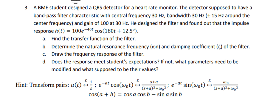
Transcribed Image Text:3. A BME student designed a QRS detector for a heart rate monitor. The detector supposed to have a
band-pass filter characteristic with central frequency 30 Hz, bandwidth 30 Hz (± 15 Hz around the
center frequency) and gain of 100 at 30 Hz. He designed the filter and found out that the impulse
response h(t) = 100e¬40t cos(180t + 12.5°).
a. Find the transfer function of the filter.
b. Determine the natural resonance frequency (on) and damping coefficient (5) of the filter.
Draw the frequency response of the filter.
C.
d. Does the response meet student's expectations? If not, what parameters need to be
modified and what supposed to be their values?
Hint: Transform pairs: u(t) é÷ ; e
e-at cos(wot) A
sta
;; e-at
sin(wot) →
wo
(s+a)²+wo²
cos(a + b) = cos a cos b – sin a sin b
(s+a)²+w,²
Expert Solution
This question has been solved!
Explore an expertly crafted, step-by-step solution for a thorough understanding of key concepts.

Step by step
Solved in 2 steps with 4 images

Knowledge Booster


Learn more about
Need a deep-dive on the concept behind this application? Look no further. Learn more about this topic, electrical-engineering and related others by exploring similar questions and additional content below.Recommended textbooks for you
Introductory Circuit Analysis (13th Edition)
Electrical Engineering
ISBN:
9780133923605
Author:
Robert L. Boylestad
Publisher:
PEARSON

Delmar's Standard Textbook Of Electricity
Electrical Engineering
ISBN:
9781337900348
Author:
Stephen L. Herman
Publisher:
Cengage Learning

Programmable Logic Controllers
Electrical Engineering
ISBN:
9780073373843
Author:
Frank D. Petruzella
Publisher:
McGraw-Hill Education
Introductory Circuit Analysis (13th Edition)
Electrical Engineering
ISBN:
9780133923605
Author:
Robert L. Boylestad
Publisher:
PEARSON
Delmar's Standard Textbook Of Electricity
Electrical Engineering
ISBN:
9781337900348
Author:
Stephen L. Herman
Publisher:
Cengage Learning
Programmable Logic Controllers
Electrical Engineering
ISBN:
9780073373843
Author:
Frank D. Petruzella
Publisher:
McGraw-Hill Education

Fundamentals of Electric Circuits
Electrical Engineering
ISBN:
9780078028229
Author:
Charles K Alexander, Matthew Sadiku
Publisher:
McGraw-Hill Education

Electric Circuits. (11th Edition)
Electrical Engineering
ISBN:
9780134746968
Author:
James W. Nilsson, Susan Riedel
Publisher:
PEARSON

Engineering Electromagnetics
Electrical Engineering
ISBN:
9780078028151
Author:
Hayt, William H. (william Hart), Jr, BUCK, John A.
Publisher:
Mcgraw-hill Education,