3. A hybrid model amplifier is shown below. The parameters are h₁1 = 45ohms, h₂1 = 80, h₂2 = 12.5 us and h₁2 = 5 x 10⁴. Select RL so that the current gain i₂/1₁ = 79 and the input resistance of the circuit is less than 10 ohms. h11 www h2111 h22 U2 RL V1 h1202
3. A hybrid model amplifier is shown below. The parameters are h₁1 = 45ohms, h₂1 = 80, h₂2 = 12.5 us and h₁2 = 5 x 10⁴. Select RL so that the current gain i₂/1₁ = 79 and the input resistance of the circuit is less than 10 ohms. h11 www h2111 h22 U2 RL V1 h1202

Delmar's Standard Textbook Of Electricity
7th Edition
ISBN:9781337900348
Author:Stephen L. Herman
Publisher:Stephen L. Herman
Chapter18: Resistive-inductive Parallel Circuits
Section: Chapter Questions
Problem 13PP: In an R-L parallel circuit, IT=1.25 amps, R=1.2k, and XL=1k. Find IR

Related questions
Question
3 answer it with complete details ASAP will give thumbs up
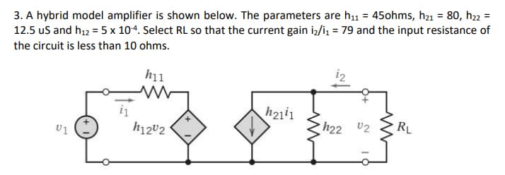
Transcribed Image Text:3. A hybrid model amplifier is shown below. The parameters are h₁1 = 45ohms, h₂1 = 80, h₂2 =
12.5 us and h₁2 = 5 x 10⁻⁴. Select RL so that the current gain i₂/1₁ = 79 and the input resistance of
the circuit is less than 10 ohms.
h11
www
h2111
h22 02
RL
U1
i₁
h1202
Expert Solution
This question has been solved!
Explore an expertly crafted, step-by-step solution for a thorough understanding of key concepts.

Step by step
Solved in 2 steps with 1 images

Knowledge Booster


Learn more about
Need a deep-dive on the concept behind this application? Look no further. Learn more about this topic, electrical-engineering and related others by exploring similar questions and additional content below.Recommended textbooks for you
Delmar's Standard Textbook Of Electricity
Electrical Engineering
ISBN:
9781337900348
Author:
Stephen L. Herman
Publisher:
Cengage Learning
Delmar's Standard Textbook Of Electricity
Electrical Engineering
ISBN:
9781337900348
Author:
Stephen L. Herman
Publisher:
Cengage Learning