3. PRELIMINARY WORK 1. Calculate the cut off frequencies and central frequency of the circuit given in Figure 1 with C=10 uF, R= 20 2 and L-1 mH. 2. Plot the gain (VotV,) of the circuit versus frequency. 3. Calculate bandwidth of the filter. Please note that signal source has 50 ohm impedance, so that you have to take total resistance of the circuit as 50+20=70 ohm value for calculation, not only 20 ohm.
3. PRELIMINARY WORK 1. Calculate the cut off frequencies and central frequency of the circuit given in Figure 1 with C=10 uF, R= 20 2 and L-1 mH. 2. Plot the gain (VotV,) of the circuit versus frequency. 3. Calculate bandwidth of the filter. Please note that signal source has 50 ohm impedance, so that you have to take total resistance of the circuit as 50+20=70 ohm value for calculation, not only 20 ohm.

Introductory Circuit Analysis (13th Edition)
13th Edition
ISBN:9780133923605
Author:Robert L. Boylestad
Publisher:Robert L. Boylestad
Chapter1: Introduction
Section: Chapter Questions
Problem 1P: Visit your local library (at school or home) and describe the extent to which it provides literature...

Related questions

Question
Transcribed Image Text:EXPERIMENT 6
BAND-PASS FILTERS
1. AIM OF THE EXPERIMENT
To obtain frequency characteristic of the band
pass
filter.
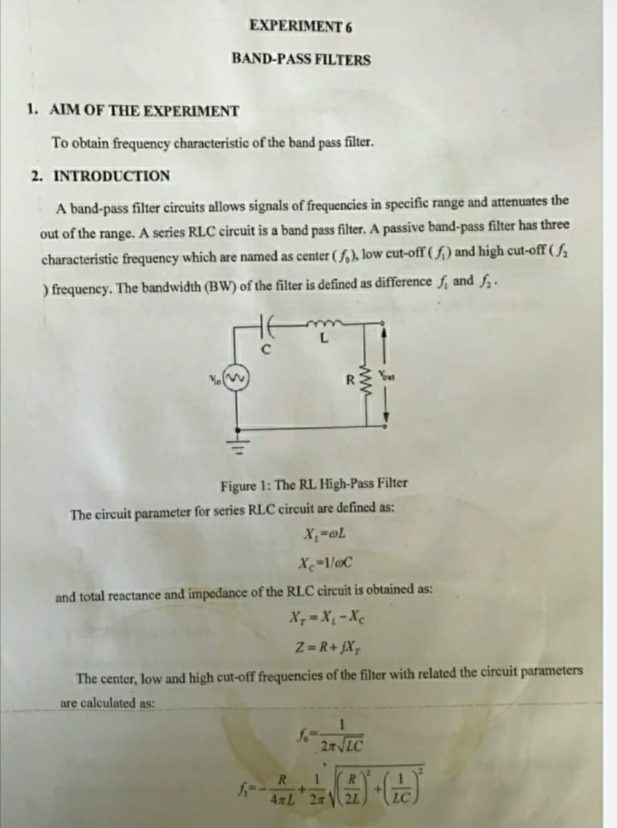
2. INTRODUCTION
A band-pass filter circuits allows signals of frequencies in specific range and attenuates the
out of the range. A series RLC circuit is a band pass filter. A passive band-pass filter has three
characteristic frequency which are named as center ( f.), low cut-off ( f;) and high cut-off ( f
) frequency. The bandwidth (BW) of the filter is defined as difference f, and f.
L.
Figure 1: The RL High-Pass Filter
The circuit parameter for series RLC circuit are defined as:
X=1/@C
and total reactance and impedance of the RLC circuit is obtained as:
X, = X, -Xc
Z = R+ jX,
The center, low and high cut-off frequencies of the filter with related the circuit parameters
are calculated as:
1
fo
27 LC
R.
4 L 2n
2L
LC
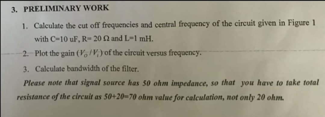
Transcribed Image Text:3. PRELIMINARY WORK
1. Calculate the cut off frequencies and central frequency of the circuit given in Figure 1
with C=10 uF, R= 20 2 and L=1 mH.
2. Plot the gain (VotV;) of the circuit versus frequency.
3. Calculate bandwidth of the filter.
Please note that signal source has 50 ohm impedance, so that you have to take total
resistance of the circuit as 50+20=70 ohm value for calculation, not only 20 ohm.
Expert Solution
This question has been solved!
Explore an expertly crafted, step-by-step solution for a thorough understanding of key concepts.

Step by step
Solved in 2 steps with 1 images

Knowledge Booster


Learn more about
Need a deep-dive on the concept behind this application? Look no further. Learn more about this topic, electrical-engineering and related others by exploring similar questions and additional content below.Recommended textbooks for you
Introductory Circuit Analysis (13th Edition)
Electrical Engineering
ISBN:
9780133923605
Author:
Robert L. Boylestad
Publisher:
PEARSON

Delmar's Standard Textbook Of Electricity
Electrical Engineering
ISBN:
9781337900348
Author:
Stephen L. Herman
Publisher:
Cengage Learning

Programmable Logic Controllers
Electrical Engineering
ISBN:
9780073373843
Author:
Frank D. Petruzella
Publisher:
McGraw-Hill Education
Introductory Circuit Analysis (13th Edition)
Electrical Engineering
ISBN:
9780133923605
Author:
Robert L. Boylestad
Publisher:
PEARSON
Delmar's Standard Textbook Of Electricity
Electrical Engineering
ISBN:
9781337900348
Author:
Stephen L. Herman
Publisher:
Cengage Learning
Programmable Logic Controllers
Electrical Engineering
ISBN:
9780073373843
Author:
Frank D. Petruzella
Publisher:
McGraw-Hill Education

Fundamentals of Electric Circuits
Electrical Engineering
ISBN:
9780078028229
Author:
Charles K Alexander, Matthew Sadiku
Publisher:
McGraw-Hill Education

Electric Circuits. (11th Edition)
Electrical Engineering
ISBN:
9780134746968
Author:
James W. Nilsson, Susan Riedel
Publisher:
PEARSON

Engineering Electromagnetics
Electrical Engineering
ISBN:
9780078028151
Author:
Hayt, William H. (william Hart), Jr, BUCK, John A.
Publisher:
Mcgraw-hill Education,