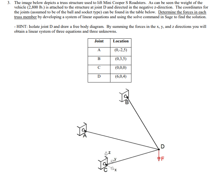
3. The image below depicts a truss structure used to lift Mini Cooper S Roadsters. As can be seen the weight of the vehicle (2,800 lb.) is attached to the structure at joint D and directed in the negative z-direction. The coordinates for the joints (assumed to be of the ball and socket type) can be found in the table below. Determine the forces in each truss member by developing a system of linear equations and using the solve command in Sage to find the solution. - HINT: Isolate joint D and draw a free body diagram. By summing the forces in the x, y, and z directions you will obtain a linear system of three equations and three unknowns. Joint Location (0,-2,5) (0,3,5) (0,0,0) (6,0,4) OF хX
3. The image below depicts a truss structure used to lift Mini Cooper S Roadsters. As can be seen the weight of the vehicle (2,800 lb.) is attached to the structure at joint D and directed in the negative z-direction. The coordinates for the joints (assumed to be of the ball and socket type) can be found in the table below. Determine the forces in each truss member by developing a system of linear equations and using the solve command in Sage to find the solution. - HINT: Isolate joint D and draw a free body diagram. By summing the forces in the x, y, and z directions you will obtain a linear system of three equations and three unknowns. Joint Location (0,-2,5) (0,3,5) (0,0,0) (6,0,4) OF хX

International Edition---engineering Mechanics: Statics, 4th Edition
4th Edition
ISBN:9781305501607
Author:Andrew Pytel And Jaan Kiusalaas
Publisher:Andrew Pytel And Jaan Kiusalaas
Chapter4: Coplanar Equilibrium Analysis
Section: Chapter Questions
Problem 4.97P: The figure shows a wire cutter. Determine the cutting force on the wire at A when the 75-N forces...

Related questions
Question
Transcribed Image Text:3. The image below depicts a truss structure used to lift Mini Cooper S Roadsters. As can be seen the weight of the
vehicle (2,800 lb.) is attached to the structure at joint D and directed in the negative z-direction. The coordinates for
the joints (assumed to be of the ball and socket type) can be found in the table below. Determine the forces in each
truss member by developing a system of linear equations and using the solve command in Sage to find the solution.
- HINT: Isolate joint D and draw a free body diagram. By summing the forces in the x, y, and z directions you will
obtain a linear system of three equations and three unknowns.
Joint
Location
(0,-2,5)
(0,3,5)
(0,0,0)
(6,0,4)
OF
хX
Expert Solution
This question has been solved!
Explore an expertly crafted, step-by-step solution for a thorough understanding of key concepts.

This is a popular solution!

Trending now
This is a popular solution!

Step by step
Solved in 7 steps with 7 images

Recommended textbooks for you
International Edition---engineering Mechanics: St…
Mechanical Engineering
ISBN:
9781305501607
Author:
Andrew Pytel And Jaan Kiusalaas
Publisher:
CENGAGE L
International Edition---engineering Mechanics: St…
Mechanical Engineering
ISBN:
9781305501607
Author:
Andrew Pytel And Jaan Kiusalaas
Publisher:
CENGAGE L