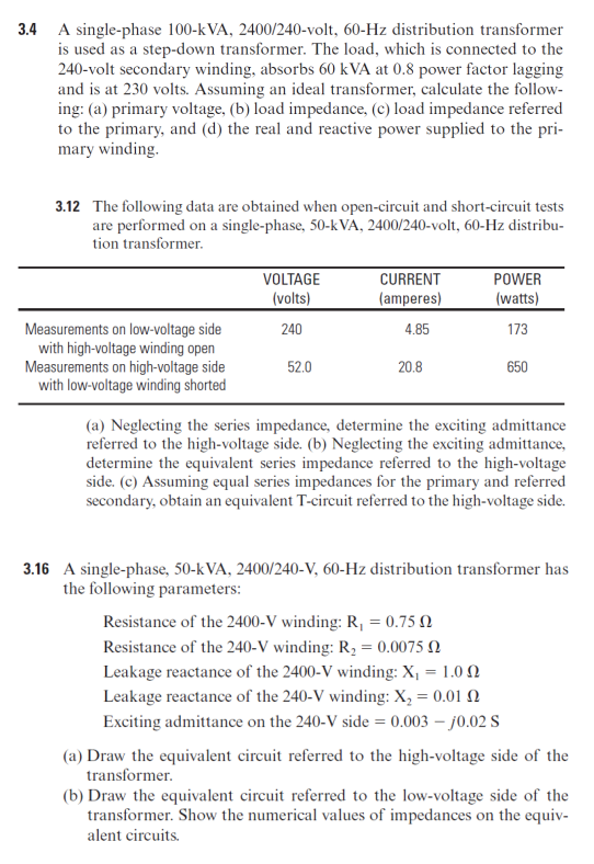
3.4 A single-phase 100-kVA, 2400/240-volt, 60-Hz distribution transformer is used as a step-down transformer. The load, which is connected to the 240-volt secondary winding, absorbs 60 kVA at 0.8 power factor lagging and is at 230 volts. Assuming an ideal transformer, calculate the follow- ing: (a) primary voltage, (b) load impedance, (c) load impedance referred to the primary, and (d) the real and reactive power supplied to the pri- mary winding.
3.4 A single-phase 100-kVA, 2400/240-volt, 60-Hz distribution transformer is used as a step-down transformer. The load, which is connected to the 240-volt secondary winding, absorbs 60 kVA at 0.8 power factor lagging and is at 230 volts. Assuming an ideal transformer, calculate the follow- ing: (a) primary voltage, (b) load impedance, (c) load impedance referred to the primary, and (d) the real and reactive power supplied to the pri- mary winding.

Power System Analysis and Design (MindTap Course List)
6th Edition
ISBN:9781305632134
Author:J. Duncan Glover, Thomas Overbye, Mulukutla S. Sarma
Publisher:J. Duncan Glover, Thomas Overbye, Mulukutla S. Sarma
Chapter3: Power Transformers
Section: Chapter Questions
Problem 3.4P: A single-phase 100-kVA,2400/240-volt,60-Hz distribution transformer is used as a step-down...

Related questions

Concept explainers
Three-Phase Transformers
Three-segment transformers are a type of transformer used to transform voltages of electrical systems into three ranges. Two type transformers are shell-type transformer and core type transformer. In brief, it could be described because of the exquisite kinds of configurations.
Transformer
Ever since electricity has been created, people have started using it in its entirety. We see many types of Transformers in the neighborhoods. Some are smaller in size and some are very large. They are used according to their requirements. Many of us have seen the electrical transformer but they do not know what work they are engaged in.
Question
Transcribed Image Text:3.4 A single-phase 100-kVA, 2400/240-volt, 60-Hz distribution transformer
is used as a step-down transformer. The load, which is connected to the
240-volt secondary winding, absorbs 60 kVA at 0.8 power factor lagging
and is at 230 volts. Assuming an ideal transformer, calculate the follow-
ing: (a) primary voltage, (b) load impedance, (c) load impedance referred
to the primary, and (d) the real and reactive power supplied to the pri-
mary winding.
3.12 The following data are obtained when open-circuit and short-circuit tests
are performed on a single-phase, 50-k VA, 2400/240-volt, 60-Hz distribu-
tion transformer.
VOLTAGE
CURRENT
POWER
(volts)
(amperes)
(watts)
Measurements on low-voltage side
with high-voltage winding open
Measurements on high-voltage side
with low-voltage winding shorted
240
4.85
173
52.0
20.8
650
(a) Neglecting the series impedance, determine the exciting admittance
referred to the high-voltage side. (b) Neglecting the exciting admittance,
determine the equivalent series impedance referred to the high-voltage
side. (c) Assuming equal series impedances for the primary and referred
secondary, obtain an equivalent T-circuit referred to the high-voltage side.
3.16 A single-phase, 50-kVA, 2400/240-V, 60-Hz distribution transformer has
the following parameters:
Resistance of the 2400-V winding: R, = 0.75 N
Resistance of the 240-V winding: R, = 0.0075 N
Leakage reactance of the 2400-V winding: X, = 1.0 0
Leakage reactance of the 240-V winding: X, = 0.01 N
Exciting admittance on the 240-V side = 0.003 – j0.02 S
(a) Draw the equivalent circuit referred to the high-voltage side of the
transformer.
(b) Draw the equivalent circuit referred to the low-voltage side of the
transformer. Show the numerical values of impedances on the equiv-
alent circuits.
Expert Solution
This question has been solved!
Explore an expertly crafted, step-by-step solution for a thorough understanding of key concepts.

Step by step
Solved in 2 steps with 1 images

Knowledge Booster


Learn more about
Need a deep-dive on the concept behind this application? Look no further. Learn more about this topic, electrical-engineering and related others by exploring similar questions and additional content below.Recommended textbooks for you
Power System Analysis and Design (MindTap Course …
Electrical Engineering
ISBN:
9781305632134
Author:
J. Duncan Glover, Thomas Overbye, Mulukutla S. Sarma
Publisher:
Cengage Learning

EBK ELECTRICAL WIRING RESIDENTIAL
Electrical Engineering
ISBN:
9781337516549
Author:
Simmons
Publisher:
CENGAGE LEARNING - CONSIGNMENT
Power System Analysis and Design (MindTap Course …
Electrical Engineering
ISBN:
9781305632134
Author:
J. Duncan Glover, Thomas Overbye, Mulukutla S. Sarma
Publisher:
Cengage Learning
EBK ELECTRICAL WIRING RESIDENTIAL
Electrical Engineering
ISBN:
9781337516549
Author:
Simmons
Publisher:
CENGAGE LEARNING - CONSIGNMENT