draw the circuit
Q: 15 Ω R1 25 0 R2 12 V 18 V 15 V( 30 Ω R3 20 Ω R4 10 2 R5 30 Ω R6 50 0 50 Rg 14 V 80 R9 8 V 15 0 R10
A:
Q: wave rectifier has Vin of 5sinwt volts and forward voltage of 0.7 volts, what is the average Vo?
A: We need to find out average value of given rectifier
Q: Using various types of transformers, give 1 impact to the end-users per type of transformer in terms…
A: NOTE:- As per our company policy, only FIRST 3 sub-parts of a Question can be answered at a time,…
Q: Determine the static resistance of the diode characteristics labelled A as shown in the figure. *
A:
Q: -at Hw A signal FLE = 2e ult) is applied to the input of.. System have frequency transfer funehiom…
A:
Q: Calculate the value of voltage regulation of a power supply used by an engineer in his prototype.…
A:
Q: Q3//For the network of following Fig., determine: a. re. b. Zj. Z, (r. = 0N). d. A, (r, = ∞N). с.…
A: As per our company guidelines we are supposed to answer only first 3 subpart kindly repost the other…
Q: Problem [5] Use nodal analysis to determine Vx. 20 2 Va j10 2 + 4 Vy () 3/0° A 20 2 V,
A:
Q: 1. In FM modulation, when the frequency deviation is increased, the transmitted power would be a)…
A:
Q: The total gain of a cascaded system is determine of the gains of each stage. the O a. product O b.…
A:
Q: Explain this. it is a -4 poles -26 conductors -double layer -simplex wave winding
A: Two figures of armature winding design is given. We need to explain whether it is 4 poles, 26…
Q: Sketch the following periodic signal: x(t) = A over the period t=0 to t=1 sec, x(t) = 0 over the…
A:
Q: |(ii) For the Fig. 1 as shown below find the output voltage (Vout) in terms of V (Volts) dBV of an…
A: ii) To find the output voltage (Vout)
Q: ermine the current in the 6 onms resistor using superposidon theorem. - jin
A:
Q: 3. Determine the voltage (V1) at the first resistor (R1 2.41 2) for the circuit diagram below. %3D…
A:
Q: Exumple - ind the exponential Fourier Series and plot the Freguency spectrum for fall ware rectiRiee…
A: The given sine wave is shown below:
Q: (b) For a digital-analog converter, sketch a five-stage ladder network using 10 k2 and 20 k2. (c)…
A: DAC and ADC are code converter The resolution is change in output when input digit change. It is…
Q: A series RLC circuit is operated at a frequency different from its resonant frequency. The operating…
A:
Q: Problem #16: A substation operating at full load of 1200 kVA supplies a load at 0.7 power factor…
A:
Q: Problem No. 2 (P2) A BJT amplifier with in a voltage divider bias configuration has the following…
A: We need to find out emitter resistance .
Q: Explain this diagram
A: According to the question, we need to explain the two-stage OP-AMP circuit as shown below
Q: Q1a Voltage control – fault level • A load bus (bus-L) is suppling from two different buses A & B…
A:
Q: 1. Consider the voltage divider circuit for biasing an n-channel D-MOSFET. Given the following…
A: We need to find out drain current and voltage for given circuit
Q: 1. Suppose you are developing a causal linear phase FIR filter. The length of impulse response is 25…
A: According to the question, for a causal linear phase FIR filter, we need to find the true and false…
Q: Determine the dynamic AC resistance of the diode characteristics with a 2mA of current using the…
A:
Q: Do you know how a diode and an LED are related to semiconductors? Put the symbol on a graph, along…
A:
Q: Reduce the block diagram shown R(s) V (s) V½(s) + V3(s) V¼(s) + Vs(s) C(s) G(s) G2(s) G3(s) V-(s)…
A:
Q: onsider the following control system. R(s) Y(s) K 160 s+32 K2 Find the condition for K, and K2,…
A:
Q: 6. Two infinitely long, parallel wires carry 6 A currents in opposite directions. Determine th…
A: In this question we will find magnetic flux density at point P due to two infinitely long parallel…
Q: 29. For the two-stage, capacitively coupled amplifier in Figure 6-57, find the following values: (a)…
A: Given A two stage amplifier,we need to find individual voltage gains and overall voltage gain of…
Q: Find the Thevenin and Norton equivalent circuits. 4/0° A 8Ω /10 2 Vm=33.9257.99 V Z =8.99+ j4.38 2…
A: The solution is given below
Q: iii) Calculate and write down the first 3 terms (starting at n=0) in the sequence y[n], if:
A: We need to find out the value of given sequence
Q: Zeg 1-j2 1+j3 2 1+j2 2 j5 2 Find Zeq for this circuit. Show all your work.
A: All the impedance are parallel and share the common node with P and R Given Z1 = 1-j Ω , Z2 = 1+j2…
Q: 2b What speed would result if the pump rpm is increased to produce a pumping head of 120 ft,…
A:
Q: ator was designed using ass5 cy of the out Put signal should 1.duty cycle y ourdesgin ternal…
A:
Q: Q1: A single core 66 kV cable working on three phase system has a conductor diameter of 2 cm and a…
A: Given, V=66KV Sheath Diameter (D)=5.3cm conductor diameter (d)=2 According to the equation,…
Q: A full-wave half-controlled bridge has a supply voltage of 220V at 50Hz. The firing angle delay α =…
A:
Q: Q3//For the network of following Fig.., determine: a. re. b. Z. c. Z, (r. = 1). d. A, (r, = 1).
A: As per our company guidelines we are supposed to answer only first 3 subpart kindly repost the other…
Q: If connected to a 3 V potential difference, a certain resistor dissipates O.5 W. How much energy…
A:
Q: Four point charges are placed at the corners of a rectangle as shown below. Find the resultant…
A: Electric Field :The electric field is generated by charge or by time-varying magnetic field , each…
Q: Problem 28: Find the average power loss and power factor for each of the circuits whose input…
A: We need to find out power and power factor for given voltage and current
Q: A 3phase 50 hz star connected , 2000 KVA 2300 V alternator gives a short circuit current of 600 A…
A:
Q: Obtain the inverse Laplace transform of the functions defined below (RUN # III), by hand if possible…
A:
Q: Series - Parellel Circuit 85 2 100 200 R 25 35 40 묘 Ω 12 V
A:
Q: Three types of electric devices A, B, and C are connected in series across a 115-volt ac source, and…
A: In thid question we will find given device types with given information...
Q: Semiconductors having band gap near 1.5 eV are preferred for solar cells because, select the best…
A: High band gap devices are used in solar cells because it absorb the maximum number of photons from…
Q: Q1: K(1+as) The bode plot of a transfer function G(s) is shown below. Determine the value of K, a,…
A:
Q: 5A 2Ix ΙΩ ww
A:
Q: 42. Calculate the average power delivered to the 400 m2 and 21 2 resistors, respectively, in the…
A: We need to find out power delivered to given resistor .
Q: P1. 31. Given vectors A- 2j + k; B-8i + gk: C-i- 5j + 13k. Determine (AxB) C. Select one: а. 186 O…
A:
draw the circuit and solve the following
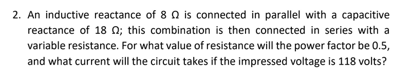
Step by step
Solved in 2 steps with 2 images
- Inductive reactance, resistance, and impedance are all measured in ohms. What is the common characteristic that makes this possible?What is the value of the independent current source in terms of ambient currents?A resistor, in series with a 138-microfarad capacitor, is connected to a 60-cycle source.If the voltage drop across the capacitor is 115 volts and the power taken by the circuitis 922 watts, calculate (a) the circuit current, (b) the ohmic value of the resistor, (c) theline voltage, (d) the circuit power factor. draw the circuit diagram
- 1. A resistor, in series with a 138-microfarad capacitor, is connected to a 60-cycle source. If the voltage drop across the capacitor is 115 volts and the power taken by the circuit is 922 watts, calculate (a) the circuit current, (b) the ohmic value of the resistor, (c) the line voltage, (d) the circuit power factor. Please show complete solution and the circuit diagram. Please round off answers up to the 3rd decimal place. Thank you!1. Describe the difference between regular (ohmic) resistors and non-linear/negativecomponents. How would the presence of a non-linear or negative component changehow you might analyze a circuit?In the circuit in Figure 2, the capacitor and The circuit of resistance is defined as a load circuit. A) Find the average power dissipated by the load circuit. B) How much of the average power calculated in a) by the resistance in the load circuit and how much spent by the capacitor? Comment on the results obtained? c) In the circuit in Figure 2, with a resistance of 80 Ω 2/3π H coil of is connected in series. In this case, Calculate the transformer ratio (n) to optimize power distribution to the load? Obtained comment on the result? D) Calculate the complex power and reactive power dissipated by the load in the newly created circuit.
- Question lets assume:Vd=300V, D=0.5 I0=30A fs=100kHz Vswitch drop =0.0V And the figure 1 below has a extra magnetizing winding. (i) Calculate the rated output power and equivalent load resistance. (ii) If IL=IL,max –IL,min is equal to 0.2A. Calculate L, when VL=V0 (iii) Sketch the current and voltage waveform of an inductance for the converter circuit shown in figure (1)An inductance of 2 henries and a resistance of20 ohms are connected in series with an emfof E volts. If the current is zero at time, t = 0,find the current at the end of 0.01 sec if E =100sin150t volts.Materials in parallel, supplying a load of 500 amps, with a terminal voltage of 240 volts, and the resistance of the product circuit 0.04 Ohm The resistance of the field circuit is 60 ohms. Calculate a. Product current b. field current c. electromotive force
- Identify the characteristics of AC and DC voltage. Runs at a higher temperature Answer 1Choose...DCAC More dangerous to transfer Answer 2Choose...DCAC Easy to produce Answer 3Choose...DCAC Easier to transform voltages Answer 4Choose...DCAC Voltage remains at a constant value Answer 5Choose...DCAC Cheaper to produceIf all impedances in Figure Q2 are 15+j45 Ω. Calculate the neutral line current.How much resistance must be put in series with a 40-microfarad-capacitor connected to a 110 volt, 120-cycle source to limit the current to 3 amperes? What will be the drop across the capacitor and across the resistor? How much power is expended?