3ft -4fi- -- 4 ft- -40 1200 1b 200 lb

Steel Design (Activate Learning with these NEW titles from Engineering!)
6th Edition
ISBN:9781337094740
Author:Segui, William T.
Publisher:Segui, William T.
Chapter10: Plate Girders
Section: Chapter Questions
Problem 10.4.4P

Related questions
Question
100%
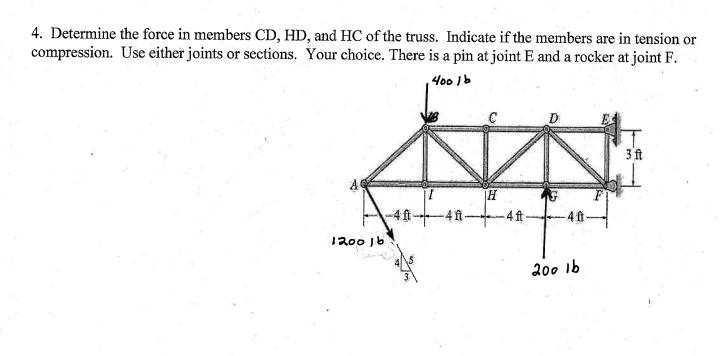
Transcribed Image Text:4. Determine the force in members CD, HD, and HC of the truss. Indicate if the members are in tension or
compression. Use either joints or sections. Your choice. There is a pin at joint E and a rocker at joint F.
400 1b
3 ft
-4 ft-
-4fi
-4ft-
1200 jb
200 1b
Expert Solution
This question has been solved!
Explore an expertly crafted, step-by-step solution for a thorough understanding of key concepts.

Step by step
Solved in 2 steps with 2 images

Knowledge Booster


Learn more about
Need a deep-dive on the concept behind this application? Look no further. Learn more about this topic, civil-engineering and related others by exploring similar questions and additional content below.Recommended textbooks for you
Steel Design (Activate Learning with these NEW ti…
Civil Engineering
ISBN:
9781337094740
Author:
Segui, William T.
Publisher:
Cengage Learning
Steel Design (Activate Learning with these NEW ti…
Civil Engineering
ISBN:
9781337094740
Author:
Segui, William T.
Publisher:
Cengage Learning