4. A 250kVA, 1500/150V, 50Hz transformer has an impedance of Z₁ = 4+ 2) and Z- 4.8+2.3j0 respectively. a) Determine the value of the secondary voltage at full lead for lagging power factor of 0.95 and rated voltage applied to the primary b) Calculate voltage regulation
4. A 250kVA, 1500/150V, 50Hz transformer has an impedance of Z₁ = 4+ 2) and Z- 4.8+2.3j0 respectively. a) Determine the value of the secondary voltage at full lead for lagging power factor of 0.95 and rated voltage applied to the primary b) Calculate voltage regulation

Power System Analysis and Design (MindTap Course List)
6th Edition
ISBN:9781305632134
Author:J. Duncan Glover, Thomas Overbye, Mulukutla S. Sarma
Publisher:J. Duncan Glover, Thomas Overbye, Mulukutla S. Sarma
Chapter6: Power Flows
Section: Chapter Questions
Problem 6.29P

Related questions
Question
Please answer in typing format
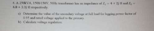
Transcribed Image Text:4. A 250kVA, 1500/150V, 50Hz transformer has an impedance of Z₁ = 4+ 2) and Z-
4.8+2.3j0 respectively.
a) Determine the value of the secondary voltage at full lead for lagging power factor of
0.95 and rated voltage applied to the primary
b) Calculate voltage regulation
Expert Solution
This question has been solved!
Explore an expertly crafted, step-by-step solution for a thorough understanding of key concepts.

Step by step
Solved in 2 steps

Recommended textbooks for you
Power System Analysis and Design (MindTap Course …
Electrical Engineering
ISBN:
9781305632134
Author:
J. Duncan Glover, Thomas Overbye, Mulukutla S. Sarma
Publisher:
Cengage Learning

Electricity for Refrigeration, Heating, and Air C…
Mechanical Engineering
ISBN:
9781337399128
Author:
Russell E. Smith
Publisher:
Cengage Learning
Power System Analysis and Design (MindTap Course …
Electrical Engineering
ISBN:
9781305632134
Author:
J. Duncan Glover, Thomas Overbye, Mulukutla S. Sarma
Publisher:
Cengage Learning
Electricity for Refrigeration, Heating, and Air C…
Mechanical Engineering
ISBN:
9781337399128
Author:
Russell E. Smith
Publisher:
Cengage Learning