a circuit that has two 2-bit unsigned integers X=x1x0 and Y=y1y0 as input. The circuit provides two output functions. The first function, a single bit, is called CLOSE. CLOSE is to be one if |X - Y ≤1, and 0 otherwise. The second function is the 2-bit difference D=d1d0 that equals X - Y if X>Y, and 00 if X
a circuit that has two 2-bit unsigned integers X=x1x0 and Y=y1y0 as input. The circuit provides two output functions. The first function, a single bit, is called CLOSE. CLOSE is to be one if |X - Y ≤1, and 0 otherwise. The second function is the 2-bit difference D=d1d0 that equals X - Y if X>Y, and 00 if X

Introductory Circuit Analysis (13th Edition)
13th Edition
ISBN:9780133923605
Author:Robert L. Boylestad
Publisher:Robert L. Boylestad
Chapter1: Introduction
Section: Chapter Questions
Problem 1P: Visit your local library (at school or home) and describe the extent to which it provides literature...

Related questions
Question
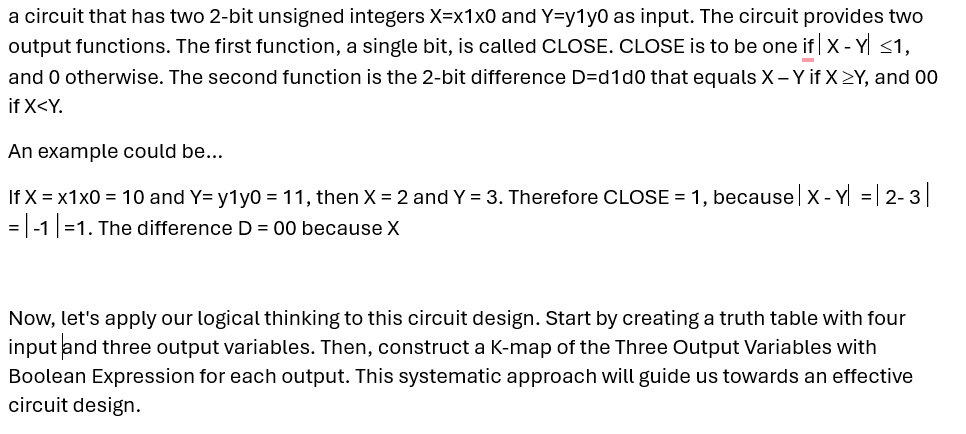
Transcribed Image Text:a circuit that has two 2-bit unsigned integers X=x1x0 and Y=y1y0 as input. The circuit provides two
output functions. The first function, a single bit, is called CLOSE. CLOSE is to be one if |X - Y ≤1,
and 0 otherwise. The second function is the 2-bit difference D=d1d0 that equals X - Y if X>Y, and 00
if X<Y.
An example could be...
If x = x1x0 = 10 and Y= y1y0 = 11, then X = 2 and Y = 3. Therefore CLOSE = 1, because | X - Y| = | 2-3
=-1 |=1. The difference D = 00 because X
Now, let's apply our logical thinking to this circuit design. Start by creating a truth table with four
input and three output variables. Then, construct a K-map of the Three Output Variables with
Boolean Expression for each output. This systematic approach will guide us towards an effective
circuit design.
Expert Solution
This question has been solved!
Explore an expertly crafted, step-by-step solution for a thorough understanding of key concepts.

Step by step
Solved in 2 steps

Recommended textbooks for you
Introductory Circuit Analysis (13th Edition)
Electrical Engineering
ISBN:
9780133923605
Author:
Robert L. Boylestad
Publisher:
PEARSON

Delmar's Standard Textbook Of Electricity
Electrical Engineering
ISBN:
9781337900348
Author:
Stephen L. Herman
Publisher:
Cengage Learning

Programmable Logic Controllers
Electrical Engineering
ISBN:
9780073373843
Author:
Frank D. Petruzella
Publisher:
McGraw-Hill Education
Introductory Circuit Analysis (13th Edition)
Electrical Engineering
ISBN:
9780133923605
Author:
Robert L. Boylestad
Publisher:
PEARSON
Delmar's Standard Textbook Of Electricity
Electrical Engineering
ISBN:
9781337900348
Author:
Stephen L. Herman
Publisher:
Cengage Learning
Programmable Logic Controllers
Electrical Engineering
ISBN:
9780073373843
Author:
Frank D. Petruzella
Publisher:
McGraw-Hill Education

Fundamentals of Electric Circuits
Electrical Engineering
ISBN:
9780078028229
Author:
Charles K Alexander, Matthew Sadiku
Publisher:
McGraw-Hill Education

Electric Circuits. (11th Edition)
Electrical Engineering
ISBN:
9780134746968
Author:
James W. Nilsson, Susan Riedel
Publisher:
PEARSON

Engineering Electromagnetics
Electrical Engineering
ISBN:
9780078028151
Author:
Hayt, William H. (william Hart), Jr, BUCK, John A.
Publisher:
Mcgraw-hill Education,