4. Considering the state of stress at a certain location of a structure, as shown in Figure 4, a) determine the center, C, the reference point, A of the Mohr's circle, draw the Mohr's circle (clearly indicate points A and C, the radius R, the reference axis, and o & Taxes with units) and determine R, Using the Mohr's circle you have drawn, b) determine the principal stresses ₁ and 2 and their respective angles, p1 and 8p2, and show them on the Mohr's circle. c) determine the in-plane maximum shear stress, T max, the inplane associated normal stress, and the angle 051, d) determine the absolute maximum shear stress Tabs, max e) draw the principal stress element (2D) with its respective orientation as measured from the reference axis drawn horizontally and f) maximum in-plane shear stress element with its appropriate orientations as measured from the reference axis 140 MPa Figure 4 40 MPa 60 MPa
4. Considering the state of stress at a certain location of a structure, as shown in Figure 4, a) determine the center, C, the reference point, A of the Mohr's circle, draw the Mohr's circle (clearly indicate points A and C, the radius R, the reference axis, and o & Taxes with units) and determine R, Using the Mohr's circle you have drawn, b) determine the principal stresses ₁ and 2 and their respective angles, p1 and 8p2, and show them on the Mohr's circle. c) determine the in-plane maximum shear stress, T max, the inplane associated normal stress, and the angle 051, d) determine the absolute maximum shear stress Tabs, max e) draw the principal stress element (2D) with its respective orientation as measured from the reference axis drawn horizontally and f) maximum in-plane shear stress element with its appropriate orientations as measured from the reference axis 140 MPa Figure 4 40 MPa 60 MPa

Mechanics of Materials (MindTap Course List)
9th Edition
ISBN:9781337093347
Author:Barry J. Goodno, James M. Gere
Publisher:Barry J. Goodno, James M. Gere
Chapter7: Analysis Of Stress And Strain
Section: Chapter Questions
Problem 7.4.4P: An element on the top surface of the fuel tanker in Problem 7.2-1 is in biaxial stress and is...

Related questions

Question
100%
4
Transcribed Image Text:4.
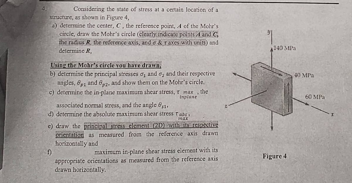
Considering the state of stress at a certain location of a
structure, as shown in Figure 4,
a) determine the center, C, the reference point, A of the Mohr's
circle, draw the Mohr's circle (clearly indicate points A and C,
the radius R, the reference axis, and o & Taxes with units) and
determine R,
Using the Mohr's circle you have drawn,
b) determine the principal stresses ₁ and 2 and their respective
angles, Op1 and 8p2, and show them on the Mohr's circle.
c) determine the in-plane maximum shear stress, T max, the
inplane
associated normal stress, and the angle 051,
d) determine the absolute maximum shear stress Tabs,
max
e) draw the principal stress element (2D) with its respective
orientation as measured from the reference axis drawn
horizontally and
f)
maximum in-plane shear stress element with its
appropriate orientations as measured from the reference axis
drawn horizontally.
140 MPa
Figure 4
40 MPa
60 MPa
Expert Solution
This question has been solved!
Explore an expertly crafted, step-by-step solution for a thorough understanding of key concepts.

This is a popular solution!

Trending now
This is a popular solution!

Step by step
Solved in 3 steps with 2 images

Knowledge Booster


Learn more about
Need a deep-dive on the concept behind this application? Look no further. Learn more about this topic, mechanical-engineering and related others by exploring similar questions and additional content below.Recommended textbooks for you
Mechanics of Materials (MindTap Course List)
Mechanical Engineering
ISBN:
9781337093347
Author:
Barry J. Goodno, James M. Gere
Publisher:
Cengage Learning
Mechanics of Materials (MindTap Course List)
Mechanical Engineering
ISBN:
9781337093347
Author:
Barry J. Goodno, James M. Gere
Publisher:
Cengage Learning