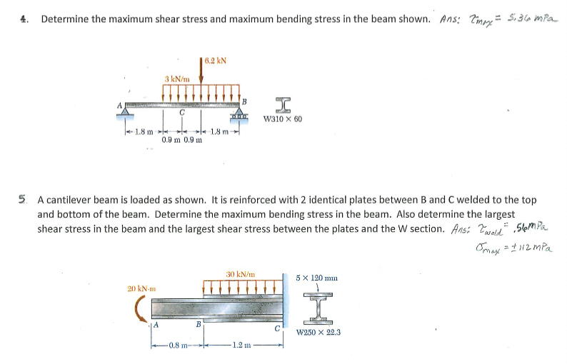
4. Determine the maximum shear stress and maximum bending stress in the beam shown. Ans: Timmy= 5,36 impa 6.2 kN 3 kN/m W310 x 60 18 m e 18 m 0.9 m 0.9 m
Q: Consider the given beam and loading where P= 78 kN/m. (For W250 x 8o, S= 983 x 103 mm3.) 12 kN m D…
A: Draw the free-body diagram of the beam. Apply force equilibrium in a vertical direction.…
Q: Determine the bending stress (in Pa) at the top of the beam at point C for the beam shown belowif P…
A:
Q: e unsymmetrical built-up section of the given dimensions supports the ven load shown. Determine the…
A: Load distribution on beam -∑MA=0⇒12×6×3+6×3×2.5+10×1+7×6=4RB⇒RB=78.25KN
Q: Beam cross section is shown below. If a resultant shear force, V acting at the beam cross section is…
A:
Q: Determine the minimum height of the beam shown below if the flexural stress is not to exceed 22MPa…
A:
Q: 15mm 1. If the maximum bending stress in the shown beam is (Omax=20 MPa),the normal stress at point…
A: 1. c) 17.86 Mpa 2. a) 250*650 mm
Q: Wo d B C kN/m Answer: Wo
A:
Q: A beam subjected to pure bending moment M = 50j + 100k kN-m has a channel section as shown below on…
A:
Q: Q2) Shear force and Moment (M) Diagram along beam ABCDEF 2AN 2m 2m 2m
A:
Q: 3. The section shown below, is subjected to a maximum shear and bending of 10 kips and 35 kips-ft,…
A: Find the normal and shear stress.
Q: Determine the internal shear and moment acting at a section passing through point C n the beam shown…
A: Solution: Area of under the loading diagram gives the total load acting on the beam and the position…
Q: Flexural Members A simply supported wood beam having a length of 24 ft and rectangular in cross…
A:
Q: - As illustrated in the diagram, a cantilever beam supports a uniform distributed load of 60 kN/m.…
A:
Q: Determine the maximum bending and shearing (Omax = 94.7 MN/m² stresses developed in the beam (t)max…
A: Let horizontal and vertical reactions at joint A be 'HA' and 'VA'. There is only roller support at…
Q: Question 1: Determine the displacement at C and the slope at B. E= 200 GPa, I = 70(10°) mm“ by using…
A: as per our guidelines. I am giving the answer of 1st question. if you want to know the solution of…
Q: For the beam and loading shown, determine the maximum bending stress on a transverse section at C.…
A:
Q: I₂ = 18×106 mm¹ 2.40 m 23.20 kN-m 180.00 mm 1 For the beam and cross section shown, compl maximum…
A: GivenM=23.20 kNm=23.20×10⁶ NmmIz=18×106 mm4y¯1=180mmy¯2=120mm
Q: = Q2/ If positive M of 20kN.m is applied, draw the bending stress distribution. Est 200GPa and EAlu…
A: Explanation: First, convert the steel section into the equivalent wooden section using the modular…
Q: Determine the maximum bending stress and shear stress of the beam shown as shown in the figure.
A: Given beam with reactions at pin and roller support is shown below. As the load is uniform, both…
Q: HW. Determine the meximum bending stress location along the beam. any at 200 m 30 700 N/m 500 N.m 30…
A:
Q: The wood beam supports loads of w = 410 Ib/ft and P = 840 lb on span lengths of LAB = 10.8 ft, LBC =…
A:
Q: For the beam and loading shown, draw the shear force and bending moment diagrams of the beam AC.…
A: The free-body diagram of the beam is given as, In this diagram, 2 kN load is displaced at point C…
Q: Q2/ If positive M of 20kN.m is applied, draw the bending stress distribution. Est = %3D 200GPA and…
A:
Q: A beam is subjected to equal 12.1 kip-ft bending moments. Assume t = t2 = tw= 2 in., d = 12 in., b1…
A: Answer: (a) Y = 5.5 in. ; Iz = 683.33 in4 ;. Sz = 105.1282 in3. (b) Bending stress at point H is…
Q: For the beam and loading shown, if d= 250 mm, detemine: (a) The magnitude of the normal stress due…
A: SFD and BMD:
Q: The channel beam with b= 300 mm, h=150 mm, and constant thickness of t=15 mm is subjected to a shear…
A: Given data:- Shear force, V=15 kN
Q: The channel beam with b= 300 mm, h=150 mm, and constant thickness of t=15 mm is subjected to a shear…
A: Given Data:- Magnitude of shear force, V=65 kN
Q: A beam is subjected to equal 14.3 kip-ft bending moments. Assume t₁ = t₂=tw 2 in., d = 14 in., b₁ =…
A: "Since you have posted a question with multiple subparts, we will solve the first three sub-parts…
Q: The simple beam with overhang carries a uniform load, w (kN/m) and a force P (kN). (aj vetemine the…
A: Please refer to the detailed solution given below, Answers - Max Stress in tension = 52.43 MPa Max…
Q: The steel beam has the cross section shown. The beam length is L = 17 ft, and the cross-sectional…
A:
Q: The steel beam has the cross section shown. The beam length is L= 18 ft, and the cross-sectional…
A:
Q: A beam is subjected to equal 13 kip-ft bending moments. Assume t₁ = t₂=tw 2 in., d = 15 in., b₁ = 6…
A:
Q: 360 N/m | 600 N 420 N D A B E 1m 0.3 m 0.5 m- 0.2 m Fig. P7.64 7.64 and 7.65 For the beam and…
A: Determine reaction at A and E by using equilibrium condition Net moment at A will be zero Net…
Q: The beam is constructed from four pieces of wood, glued together as shown. If M = 10 kip # ft,…
A: Apply flexural formulae σ=MyITo find the minimum value of bending stressM=10 kips-ft=120Kips-iny=4…
Q: For the beam shown, calculate the magnitude of the bending stress (in psi) at the bottom of the beam…
A:
Q: 8 ft The cantilevered beam above is subjected to a single point force P = 20 kip at its free end.…
A:
Q: QUESTION 1 A beam of T cross section (flange 200mm x 12mm and web 320mm x 12mm) is loaded as shown.…
A:
Q: Determine the maximum bending moment magnitude for the beam shown below. Use a = 21 ft, b = 8 ft,…
A: Given Data: The magnitude of UDL load, w=6 kips/ft
Q: 0.4m The beam is subjected to a shear of y=30 kN. Determine the maximum shear stress in the beam.…
A: GivenV=30kNI section beam
Q: 95Y For the beam loaded as shown find the location and the magnitude of the maximum tensilg bending…
A: Simply supported beam is hinged at both sides and load is applied in the middle anywhere,…
Q: Maximum Bending Moment: For the beam shown, determine the value of the maximum bending moment at…
A:
Q: MPa 1. If the maximum bending stress in the shown beam is (Omax=20 MPa), the normal stress at point…
A: From bending equation we get:σy=MINow,for the beam bending moment(M) and Area moment of inertia(I)…
Q: 40 kN 8 kN/m 60° 3 m 3 m 3 m 0.3 m
A: Given:- To Find:- Internal normal force at point c (Nc) Internal bending moment at point c (Mc)…
Q: R₁ QUESTION 1 A simple beam of length 5 m carries two types of loads: a UDL of 6 kN/m is acting over…
A: Dear student, According to the guidelines, I am allowed to answer only one…
Q: Find the bending stress at point B located at mid-span of the rod 5 N/m O.Scm Ø 2 cm 0.5m. Tm 16 N
A: Consider horizontal forward & vertically upward force as (+)ve and vertically downward force as…
Q: For the beam shown, with the maximum moment and section modulus of its cross-section as reference. 8…
A:
Q: The bending moment acting on the triangular cross section of a beam is 3.6 kN m. Determine the…
A:
Trending now
This is a popular solution!
Step by step
Solved in 2 steps with 1 images
- A weight W = 4000 lb falls through a height h = 0.5 in, onto the midpoint of a simple beam of length L = 10 ft (see figure). Assuming that the allowable bending stress in the beam is = 18,000 psi and E = 30 x 10* psi, select the lightest wide-flange beam listed in Table F-l(a) in Appendix F that will be satisfactory.A rectangular beam with semicircular notches, as shown in part b of the figure, has dimensions h = 120 mm and h1= 100 mm. The maximum allowable bending stress in the plastic beam is emix = 6 M Pa, and the bending moment is M = 150 N · m. Determine the minimum permissible width bminof the beam.A simple beam with a W 10 x 30 wide-flange cross section supports a uniform load of intensity q = 3.0 kips/ft on a span of length L = 12 ft (sec figure). The dimensions of the cross section are q = 10.5 in., b = 5.81 in., t1= 0.510 in., and fw = 0.300 in. Calculate the maximum shear stress tjuly on cross section A—A located at distance d = 2.5 ft from the end of the beam. Calculate the shear stress rat point Bon the cross section. Point B is located at a distance a = 1.5 in. from the edge of the lower flange.
- A fixed-end b earn is subjected to a point load at mid-span. The beam has a rectangular cross section (assume that the h/b ratio is 2) and is made of wood (E = 11GPa). Find height h of the cross section if the maximum displacement of the beam is 2 mm. Calculate the displacement of the beam at the inflection points.The three beams shown have approximately the same cross-sectional area. Beam 1 is a W 14 X 82 with flange plates; beam 2 consists of a web plate with four angles; and beam 3 is constructed of 2 C shapes with flange plates. Which design has the largest moment capacity? Which has the largest shear capacity? Which is the most economical in bending? Which is the most economical in shear? Assume allowable stress values are: = 18 ksi and ra=11 ksi. The most economical beam is that having the largest capacity-to-weight ratio. Neglect fabrication costs in answering parts (c) and (d) above. Note: Obtain the dimensions and properties of all rolled shapes from tables in Appendix F.A simple beam ACE is constructed with square cross sections and a double taper (see figure). The depth of the beam at the supports is dAand at the midpoint is dc= 2d 4. Each half of the beam has length L. Thus, the depth and moment of inertia / at distance x from the left-hand end are, respectively, in which IAis the moment of inertia at end A of the beam. (These equations are valid for .x between 0 and L, that is, for the left-hand half of the beam.) Obtain equations for the slope and deflection of the left-hand half of the beam due to the uniform load. From the equations in part (a), obtain formulas for the angle of rotation 94at support A and the deflection Scat the midpoint.
- A frame ABCD is constructed of steel wide-flange members (W8 x 21; E = 30 x ID6 psi) and subjected to triangularly distributed loads of maximum intensity q0acting along the vertical members (see figure). The distance between supports is L = 20 ft and the height of the frame is h = 4 ft. The members are rigidly connected at B and C. Calculate the intensity of load q0 required to produce a maximum bending moment of 80 kip-in. in the horizontal member BC. If the load q0 is reduced to one-half of the value calculated in part (a), what is the maximum bending moment in member BC? What is the ratio of this moment to the moment of 80 kip-in. in part (a)?A weight W = 20 kN falls through a height h = 1,0 mm onto the midpoint or a simple beam of length L = 3 m (see figure). The beam is made of wood with square cross section (dimension don each side) and E = 12 GPa. If the allowable bending stress in the wood is °aLLow =10MPa, what is the minimum required dimensionThe hollow box beam shown in the figure is subjected to a bending moment M of such magnitude that the flanges yield but the webs remain linearly elastic. (a) Calculate the magnitude of the moment M if the dimensions of the cross section are A = 15 in., A] = 12.75 in., h = 9 in., and ey =7.5 in. Also, the yield stress is eY = 33 ksi. (b) What percent of the moment M is produced by the elastic core?
- An overhanging beam ABC with a rectangular cross section has the dimensions shown in the figure. A weight W = 750 N drops onto end C of the beam. If the allowable normal stress in bending is 45 MPa, what is the maximum height h from which the weight may be dropped? (Assume E = 12 G Pa,)A wood box beam is constructed of two 260 mm × 50 mm boards and two 260 mm × 25 mm boards (sec figure). The boards are nailed at a longitudinal spacing. b = 100 mm. If each nail has an allowable shear force F = 1200 N. what is the maximum allowable shear force Vmax?Determine the plastic modulus Z and shape factor/for a W 12 x 14 wide-flange beam. Obtain the cross-sectional dimensions and section modulus of the beam from Table F-l(a) in Appendix F.