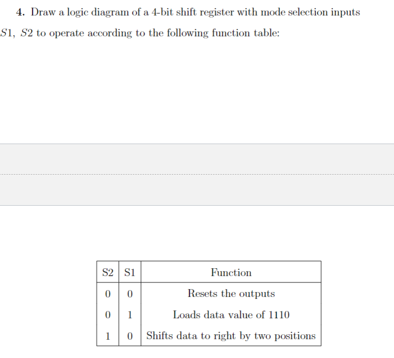
4. Draw a logic diagram of a 4-bit shift register with mode selection inputs S1, S2 to operate according to the following function table: S2 S1 Function 00 Resets the outputs 0 1 Loads data value of 1110 1 0 Shifts data to right by two positions


Q: Needs Complete solution with 100 % accuracy don't use chat gpt or ai i definitely upvote you be…
A: Step 1: if you like the solution please upvoteif you have any doubt comment herethank you
Q: Fill out the values in the table frequency, f (kHz) Results from in-Lab measurements…
A: Step 1: Step 2: Step 3: Step 4:
Q: thank you
A: First, we need to calculate the cross-sectional area ((A)) of the core. Since the depth is given as…
Q: Please answer number 1
A: #include "stm32f4xx.h"#include "stm32f4xx_exti.h"#include "stm32f4xx_syscfg.h"#include "misc.h"/*…
Q: This is a practice question from the Signal and Systems course of my Electrical Engineering Program.…
A: Step 1:Step 2:
Q: For the 4-bit binary values in the table below, show the equivalent decimal values when the data is…
A: Please comment down for any doubt. I hope my answer helps you.
Q: Consider the following state equation: [1 1 -2' x = 0 1 1 1x0u, y = [200]x Lo 0 1 1 Let u = - Kx +…
A: To find the controller gains ( K ) and ( G ) for the given state equation and desired closed-loop…
Q: Question 2: What are the minimum or maximum values of VCE,sat, VBEon, and ẞ if we assume that Ic VCE…
A: Step 1:VCEsat (Collector-Emitter Saturation Voltage):Minimum: 0.2 VMaximum: 0.4 VVBE(on)…
Q: no ai, answer step by step
A: Step 1:IF YOU HAVE ANY DOUBT YOU CAN COMMENT HERE
Q: ၁ B ☑ IB Vcc BIB E w Rc C
A: Approach to solving the question: Using the components and transistor terminals you mentioned, you…
Q: The dc converter shown in the next figure is used to control power flow from a dc voltage, Vs = 150…
A:
Q: Design a circuit that amplifies a 500 mV signal originating from a computer keyboard, so that this…
A: To amplify a 500 mV signal from a computer keyboard for interpretation by digital circuits on a…
Q: i will like
A: Part iiAssuming the system is little-endian, here are the values of r1 and r0 after the instructions…
Q: 10. Assume the initial state of the circuit shown in 01 (i.e. A = 0 and B = 1). Find the successive…
A:
Q: Find VA, VB, and Ix
A:
Q: None
A: To perform small signal analysis for the given circuit, let's denote the transconductance of the…
Q: A two-stage inverter is shown in this figure. Vs=50 V. v=110V2 sin 100 nt. The average voltage of C…
A:
Q: classify the following system for memory, Causality, stability and Linearity Yen)=2] (n-1) + x…
A: To classify the given system for memory, causality, stability, and linearity, let's analyze each…
Q: Determine the Vo of the following inverting OpAmp:
A:
Q: Using a K-Map, simplify the logic function F and construct the circuit using only NAND gates. F(x,…
A:
Q: searching for the topic of production lines and the switches in them and PLC in production lines +…
A: Step 1: Step 3: Step 4:
Q: explain plz, no ai
A: In information theory and coding theory, encoding and decoding data efficiently and reliably are…
Q: Q2. A single-phase half-bridge inverter has R-2.42 and the DC input voltage is 48V. Determine: The…
A: Drawing circuit diagrams and waveforms associated:
Q: Assuming the initial state of the shift register shown below is 101 (ie), find the successive…
A:
Q: Could you please show all work
A:
Q: Q1: If X and Y are jointly continuous random variables with probability density function f(x,y)…
A: The covariance of the random variables X and Y is: Cov(X,Y)=[∫−11∫01xy(x+y) dx dy]−E(X)E(Y)…
Q: N W h h Exercise VI Assume μ=4000μ, and assume the magnetic core saturates at Ils. Find the air gap…
A: To find the air gap length such that the new saturating current is (3Is), we can use the magnetic…
Q: Determine the value of a capacitor that has the reactance provided at the given frequency at 1.56…
A: Capacitive reactance, X=1/(wC) = 1/(2πfC) wheref= frequencyC= capacitance
Q: Please solve complete problem. I need step by step solution
A: Step 1:Step 2:Step 3: Step 4:
Q: Design and simulate series and parallel RLC circuits with LTspice to demonstrate different damped…
A: General Explanation:For a simple RLC circuit, the following parameters define the transient behavior…
Q: If a clock pulse is needed to generate a frequency of 5.64 kHZ with a duty cycle of 60%, what must…
A: Another method using online calculator
Q: b- If accidentally, one of the secondary windings get disconnected, what would be the load voltages…
A: Step 1: Label the Transformer winding to have reference and somewhat re-arranged it to easily…
Q: (ii) For the circuit in Figure 2.0a: If v(t) = 10 cos(⍵t + 0º) volts, R = 510 Ω, and C = 0.22 µF;…
A: Step 1: Step 2: Step 3: Step 4:
Q: please help me make this into a hybrid pi model.
A:
Q: Provide typed solution in step by step manner
A:
Q: Consider a system with an open loop transfer function defined by Determine the…
A: The given open loop system is Determine the expression of the phase advance corrector that must be…
Q: Let f(t) from image: We define g(t) = t2-17t a) Calculate the convolution (f*g)(t) = b) Find the…
A: (a)Step 1: Given functions are f(t)={1,−2<t<20,otherwiseand g(t)=t2−17t Step 2: Now we have…
Q: Q1: Consider the finite-length sequence 6(n) +28(n-5) x(n) (a) Find the 10-point discrete Fourier…
A: Step 1Step 2Step 3Step 4 :Step 5
Q: no ai, plz explain step by step
A: An absolutely band-limited signal and an absolutely time-limited signal are mutually exclusive. Here…
Q: I just need help with part c
A:
Q: Need correct ans with explanation
A: Detailed explanation:The provided circuit is a basic SR (Set-Reset) flip-flop made of two NOR gates…
Q: Provide supported and well justified recommendations for the adoption of the most widely used…
A: I answered this question based on the given topic you provided and did some research to support my…
Q: Calculate the Fourier transform of the following functions using the shift theorem
A: To find the Fourier transform of the given functions using the shift theorem, we need to remember…
Q: We found the following specifications of an RTD temperature sensor from the datasheet: The…
A:
Q: Find the RMS voltage of a waveform whose voltage is v(t) = 17sin(70t) Vp
A: To find the RMS voltage (Vrms) of a sinusoidal waveform, you can use the formula:Vrms=2Vpwhere…
Q: Redraw the circuit diagram of the simplified figure and find the current I flowing at resistance 8…
A:
Q: Needs Complete solution with 100 % accuracy don't use chat gpt or ai i definitely upvote you be…
A: The objective of the question is to find the base voltage in a given circuit. The circuit includes…
Q: *Construct a JK flip-flop using a D flip-flop, a two-to-one-line multiplexer, and an inverter.…
A: Step 1: Step 2: Step 3: Step 4:
Q: A square loop of wire (L = 5.45 cm) is located a distance d = 3.45 cm away from a very long,…
A: Step 1:Length is 5.45cm is 5.45×10⁻²mDistance is 3.45cm is 3.45×10⁻²mCurrent I1is 17.1mA is…
Q: 15) 63 (a) Determine the Fourier transform of the signal x(t) = exp(−t) sin(20лt) u(t), where u(t)…
A: Step 1:Step 2: Step 3: UP VOTE IF YOU LIKE THE SOLUTION.
no ai, plz draw out

Step by step
Solved in 2 steps with 1 images

- Draw a logic diagram of a 4-bit shift register with mode selection inputsS1, S2 to operate according to the following function table:Design a 4-bit arithmetic circuit, with two selection variables S1 and S0, that generates the arithmetic operations in the following table. Draw the logic diagram for a single bit stage. Note that B’ represents “Not B”. Draw the logic diagram for a single bit stagDesign a binary multiplier that multiplies two 8-bit binary number by following design rules thatshown in class. The Q and B are the two separate 8-bit binary inputs, C is the 3-bit sequence counterand R is the 16-bit result. (Note: Explain the registers that you will use to establish given process.) The steps are writing algorithm Drawing circuit undetailed (Just use the box, which have only writin under that their functions) Draw logic circuits one by one showing the internal structure of the boxes. Mahe flow chards for registers
- Design a 4-bit shifter with four d flip flops and 2 to 1 multiplexers which can implement left shift and right shift operations according to the control signal c. Draw the logic diagram. C=1 left shift and c=0 right shiftDraw a logic diagram of a 4-bit shift register, using D flip-flops, with mode selection inputsS1, S2 to operate according to the following function table: (Please provide actual diagram of the flip-flop circuit)Show how a five bit 11011 binary number can illustrated in the five-bit serial in –parallel out shift register. ...please answer in short I will like please don't reject in shorts please
- Design 2 bits counter that count down by using T flip flop when input x =1 and counts upwhen x=0. Find the following1. Derive the state table2. Derive the K‐map simplifications.3. Draw the logic diagramDesign a 4-bit arithmetic circuit, with two selection variables S1 and S0, that generates the arithmetic operations in the following table. Draw the logic diagram for a single bit stage. Note that B’ represents “Not B”. Complete the following truth table.A combinational logic circuit that compares between two 2-bit numbers A (A1 A0) and B(B1 B0) is designed. Output F is high when ? > ? and low when ? < ?. 1) Are there any undefined outputs? If there are any undefined outputs what are the inputs?
- Design a Combinational circuit with a Decoder to accept 3-bit number and generate the output binary number equal to the Square of the input number.a) Derive the truth table.b) Find simplified output function in Product of Sum(POS).c) Draw the logic diagram in logisim Simulator.1-Using the Karnaugh Method, design and draw the circuit of the logic circuit that gives the result of the multiplication of the two-bit numbers "AB" and "CD" according to minterms (SOP). Do not make any further simplifications before or after the Karnaugh Method. In tables and Karnaugh, ensure that the least significant bit is on the far right and the entries are sorted alphabetically. Make sure that the circuit you have drawn is understandable, the function you have written and the truth table are readable.I was able to fill out the truth table for part A. I ONLY need help for PART B. B) Implement the logic function (z) using the multiplexer 74HC151 shows in the picture.