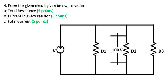
4. From the given circuit given below, solve for a. Total Resistance (5 points) b. Current in every resistor (5 points) c. Total Current (5 points) D1 तृ tot 100 V D2 ww D3
Q: Solve the given problem: 1. The Find the Fourier transform of the rectangular pulse signal x (t)…
A: We need to find out the Fourier transform for given signal .
Q: x(t1 ponont 1 ·3 3 (b) True or False For k0, the Fourier series coefficients {X[k]} are real-valued.…
A:
Q: Consider the signal x[n] shown in the figure x[n] ILII ILI 3. vialexin il y[n] 1.0 The signal y[n]…
A:
Q: 2. Applying KVL, find the value of Vi and V₂. +15 V- + K I + 10 10 V A + V/2₂ I B
A:
Q: 2 3 a) 4 5 - 7 n O 10 10 11 12 12 12 13 " 14 A 15 16 16 17 17 19 18 10 19 20 21 22 23 24 input a 0 0…
A:
Q: Find the Norton equivalent with respect to the terminals a, b for the circut in (Egute 1) Suppose…
A: We need to find out norton equivalent circuit for given , first we will find out the norton current…
Q: 1. What type of transistor is BC548? How do you identify its type based on the circuit's diagram?
A: Because the BC548 is an NPN transistor, the collector and emitter are open (reverse-biased) while…
Q: 4. In a balanced three phase system the line voltage Vab =220cis(30°) volts and line current Ic =…
A: In this question, We need to determine the power of the Delta system. Power P= 3Vph Iph cos(Vph ^…
Q: Determine the amplitude of equivalent impedance seen by the source V, in the following circuit when:…
A: To find the amplitude of equivalent impedance seen by the source Vs for the given circuit
Q: Q- A 20 MVA, 11.2 kV, 4-pole, 50 Hz alternator has an inertia constant of 15 MJ/MVA. If the input…
A: Given- 20 MVA, 11.2 kV, 4-pole, 50 Hz alternator, Machine rating G=20 MVA, Pole P=4, Frequency f=50…
Q: Please check the right statement(s) 1) The unit of J is A/m² 11) The unit of H is A/m² III) The unit…
A: We need to determine the units of current density (J), magnetic field intensity (H), Electric flux…
Q: You acquire a 20 Hz analog signal from sensor. Now you need to digitalize it to process it on an on-…
A: . SOLUTION GIVEN f = 20 Hz ( Analog Signal from Sensor) LET…
Q: Figure 5.73 For Prob. 5.36. Section 5.6 Summing Amplifier 5.37 Determine the output of the summing…
A:
Q: Critical Damping A motor coil having an inductance of 8 H is in parallel with a 2 µF capacitor and a…
A: It is given that: L=8 HC=2 μF
Q: Calculate the power dissipated in the 40 2 resistor and the voltage labeled vc in each of the…
A:
Q: A 200 volt shunt motor is rated a 5 HP and 1000 rpm. At rated output it draws 25 A of line current.…
A:
Q: Figure 1 shows a single line diagram of a part of the three-phase power system. The ratings of the…
A: Given We have to draw per unit equivalent circuit with base values Vbase,new =13.8 kV MVAbase, new…
Q: Design and implement (draw the circuit) the output f(12) of a 7 segments decoder as a function of…
A: Seven Light Emitting Diodes (LEDs) are placed in a specific pattern (common cathode or common anode…
Q: What will be the oscillator frequency of the Hartley oscillator if inductance L1, L2 are equal to…
A: We need to find out the frequency of oscillation for given oscillator .
Q: Write the KVL equation for each of the loops shown in the circuit below. VA + V1 ww + V3 MA LOOP 2…
A:
Q: Calculate the total current in the circuit below if the circuit is powered by the sine wave voltage…
A:
Q: replaced with a capacitor of 0.5 mF, how would it affect the branch current? The alternating Voltage…
A:
Q: Given that a feedback network is shunt-series, and the output load is 10kΩ, what is the output…
A: Output load = 10kΩ Transfer gain (β) = 10 Source current = 20mA Feedback current (IF) = 10mA
Q: IV. Compare the Fourier transform table specifically this part 1 e-ªu(t), a>0 jw + a 1 te-ªtu(t),…
A: We need to find out the Fourier transform for given signal .
Q: A three-phase synchronous generator has a synchronous reactance of 50 Ω/phase. It is connected to an…
A:
Q: What is the benefit of the mug angle in the thyristor?
A: Thyristor: Thyristor is a semiconducting device used in electronic circuits. Thyristors are also…
Q: Source 12V C 200 IR RL 40.0² 102 300 Given the network of resistive element as shown above,…
A:
Q: For the capacitor-input filter, calculate the capacitance C 6 μF 8 μF 10 μF 12 μF
A: The ripple is the unwanted AC quantity present in the DC output and it can be removed with the…
Q: Create 5 sample problems about ILLUMINATION and show complete solution and final answer.
A:
Q: A 100km, 60Hz transmission line has a resistance of 2.07Ω/km, an inductance of 3.108mH/km, and a…
A: Given Length of line =l=100 km resistance = 2.07Ω/km For 100 km length, total resistance is…
Q: 1. For the bridge network shown in Figure shown, find the current in the 5ohm resistor, and its…
A: We need to find out the current through given resistor by using of thevenin equivalent circuit , for…
Q: 1.A 3-phase induction motor is wound for 12 poles and is supplied from 60Hz system. Calculate: (i)…
A:
Q: A charge of 10 Chas velocity of V=2a, +32a,-4a, m/s. Find Fon the charge in the field of E=6a, + 5ā,…
A: Given that, Q=10 C E→=6 ax→+5ay→+9az→ V/m V→= 2 ax→+32ay→-4 az→ m/s Here we have to calculate only…
Q: Find VL(1) & VR(1) for t> 0. +31 €moxa Fr V₁ - 22 t=0 (1) ZA
A:
Q: Write the KCL equation at the nodes A, B, C and D marked in the circuit below. I1 Mu ww 13 mm 5A MM…
A:
Q: alculate the three currents 1₁, 12 and 13 in the circuit diagram below. 5.00 Ω www + 12.00 V www…
A:
Q: 1. Consider an ideal low-pass filter with frequency response -66 2. |w| w. The input to this filter…
A: We need to find out output for given input signal and given system .
Q: Given two vectors A = 4ax + 2.5ay – 2az and B = 5ax + 2ay + 4 az . find (a) the angle between vector…
A: It is given that: A=4ax+2.5ay-2azB=5ax+2ay+4az
Q: 2.A 3-phase motor having a star connected rotor has an induced emf of 150 volts between slip rings…
A: Given that: The 3-phase motor has star connected rotor Induced EMF 150 V at a standstill on an open…
Q: A 200 V dc shunt motor takes 20 A at rated voltage and runs at 1000 rpm. Its armature resistance is…
A:
Q: EXAMPLE 7.17 R₁ 68 ΚΩ R, < 20 ΚΩ G + VGS RD R$ ENGG CC ROT Determine ID VGS, and VDs for the…
A:
Q: 2. For the circuit shown, find, using the Kirchhoff's Law, (a) the current flowing in and the pd…
A: As per our company guidelines we are supposed to answer only first three subparts kindly repost the…
Q: Referring to figure shown below, determine the load current I₁ using Thevenin's Theorem 192 www 692…
A:
Q: 1. The capacitor in Figure 3 begins fully discharged. The switch in Figure 3 is closed at t=0 s. At…
A: The given circuit is shown below, The time, t=0.125 s
Q: A DC motor is wired as shown in the figure. If the ammeter (DC) reads 30 A, determine and report the…
A: Given information about a DC motor, Field resistance Rf=200 Ω. Armature resistance Ra=0.2 Ω. Supply…
Q: A uniform line charge with pi = 5 µC/m lies along the x axis. Using Gauss' Law find the electric…
A: We need to find out electric flux for given charge distribution .
Q: JF. Ст-
A:
Q: A silicon transistor is biased with base resistor method. If ß=100, VBE =0.7 V, zero signal…
A: Given- Current gain, β=100. Base emitter voltage, VBE=0.7 V. Collector current, IC=1 mA. VCC=6 V.…
Q: Write by inspection only the output g(t) in general terms if the input is a unit step of the system…
A:
Q: Solve for I using: a. Thevenin's Theorem b. Norton's Theorem
A: Thevenin theorem Thevenin's theorem states that any linear two-terminal circuit consisting of…
d1 = 5 d2 = 3 d3 = 10
Step by step
Solved in 3 steps with 3 images
- You are an electrician on the job. The electrical blueprint shows that eight 500-W lamps are to be installed on the same circuit. The circuit voltage is 277 V and is protected by a 20-A circuit breaker. A continuous-use circuit can be loaded to only 80% of its rating. Is a 20-A circuit large enough to carry this load?A combination of three resistors R1, R2, and R3 in series is connected across a voltage source VT. The voltage drop across R1 and R3 are 10 V and 36 V, respectively. If the current supplied by the source voltage is 1.4 A and the total power supplied by the source is 70 W, calculate the voltage drop across R2 in volts.A 10-ohm resistor is connected in series with another resistor R. This in turn is connected in series to a 12-V source. If the voltage across the 10-ohm resistor is 3 V, determine the resistance R.
- a. What should be the value of X such that the total resistance of the circuit is 22 ohms? b. What is the voltage across R4? 3. How much current is flowing through R3?Three resistances (10 ohms, 20 ohms, and 30 ohms) are connected in series with a 100-V power source. If a 50-V power source is connected parallel to the 10-ohm resistor, determine the power dissipated by the 20-ohm resistor." KIRCHHOFF'S LAW " Please Find the Current and Voltages in 6k , 3k , 6k Ohm Resistors only, with a total of 3 currents and 3 voltages to compute Using KIRCHHOFF's LAW thankyou very much ! I've included a cicruit app to check if your answer was correct and close to the value of currents and voltages thankyou!
- Q1- Determine the range of adjustable resistance, R. for a Wheatstone bridge circuit as shown in Figure Q1 that can measure voltage at range between 0 to 10 V. The voltage source is 50 V and fixed resistances, R1 = R2 = R3 = 1 K ohm, next, determine the range of current can be measured by using galvanometer with internal resistance is 200ohmA combination of three resistors R1, R2 and R3 in series is connected across a voltage source Vt. The voltage drop across R1 and R3 are 10V and 36V, respectively. If the current supplied by the source voltage is 1.4A and the total power supplied by the source is 70W, Calculate the value of Req-please solve all 4 parts Part A Find i for the circuit. Part B Find the power supplied by the voltage source. Part C Reverse the polarity of the voltage source in the circuit shown in the figure, and find i for a new circuit. Part D Reverse the polarity of the voltage source in the circuit shown in the figure, and find the power supplied by the voltage source for the new circuit.
- a. Calculate total resistance b. Calculate the total current IT c. Find the voltage VR5, with others words, the voltage drop across R5. d. Calculate IR3, in other words, the current through R3. e. Calculate the power R1 consumes.A resistor in a circuit has a value of 560 Ω. It is desired to decrease its value to 344 Ω. The resistance to be connected with it in parallel will be of? a. 740 Ω b. 1090 Ω c. 892 Ω d. 540 ΩGiven that the total resistance is 15 Ohms and the Voltage Source is 30 V: (1) Determine the current through the 18W resistance of the circuit.(2) Potential difference across the 10W resistance if a 30Vdc source is connected across the terminals.