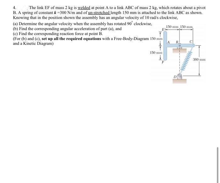
4. The link EF of mass 2 kg is welded at point A to a link ABC of mass 2 kg, which rotates about a pivot B. A spring of constant k =300 N/m and of un-stretched length 150 mm is attached to the link ABC as shown. Knowing that in the position shown the assembly has an angular velocity of 10 rad/s clockwise, (a) Determine the angular velocity when the assembly has rotated 90° clockwise, (b) Find the corresponding angular acceleration of part (a), and (c) Find the corresponding reaction force at point B. (For (b) and (c), set up all the required equations with a Free-Body-Diagram 150 mm and a Kinetic Diagram) 150 mm 150 mm, 150 mm 360 mm
4. The link EF of mass 2 kg is welded at point A to a link ABC of mass 2 kg, which rotates about a pivot B. A spring of constant k =300 N/m and of un-stretched length 150 mm is attached to the link ABC as shown. Knowing that in the position shown the assembly has an angular velocity of 10 rad/s clockwise, (a) Determine the angular velocity when the assembly has rotated 90° clockwise, (b) Find the corresponding angular acceleration of part (a), and (c) Find the corresponding reaction force at point B. (For (b) and (c), set up all the required equations with a Free-Body-Diagram 150 mm and a Kinetic Diagram) 150 mm 150 mm, 150 mm 360 mm

Elements Of Electromagnetics
7th Edition
ISBN:9780190698614
Author:Sadiku, Matthew N. O.
Publisher:Sadiku, Matthew N. O.
ChapterMA: Math Assessment
Section: Chapter Questions
Problem 1.1MA

Related questions

Question
Transcribed Image Text:4.
The link EF of mass 2 kg is welded at point A to a link ABC of mass 2 kg, which rotates about a pivot
B. A spring of constant k =300 N/m and of un-stretched length 150 mm is attached to the link ABC as shown.
Knowing that in the position shown the assembly has an angular velocity of 10 rad/s clockwise,
(a) Determine the angular velocity when the assembly has rotated 90° clockwise,
(b) Find the corresponding angular acceleration of part (a), and
(c) Find the corresponding reaction force at point B.
(For (b) and (c), set up all the required equations with a Free-Body-Diagram 150 mm
and a Kinetic Diagram)
150 mm, 150 mm,
E
150 mm
360 mm
Expert Solution
This question has been solved!
Explore an expertly crafted, step-by-step solution for a thorough understanding of key concepts.

Step by step
Solved in 6 steps with 6 images

Knowledge Booster


Learn more about
Need a deep-dive on the concept behind this application? Look no further. Learn more about this topic, mechanical-engineering and related others by exploring similar questions and additional content below.Recommended textbooks for you
Elements Of Electromagnetics
Mechanical Engineering
ISBN:
9780190698614
Author:
Sadiku, Matthew N. O.
Publisher:
Oxford University Press

Mechanics of Materials (10th Edition)
Mechanical Engineering
ISBN:
9780134319650
Author:
Russell C. Hibbeler
Publisher:
PEARSON

Thermodynamics: An Engineering Approach
Mechanical Engineering
ISBN:
9781259822674
Author:
Yunus A. Cengel Dr., Michael A. Boles
Publisher:
McGraw-Hill Education
Elements Of Electromagnetics
Mechanical Engineering
ISBN:
9780190698614
Author:
Sadiku, Matthew N. O.
Publisher:
Oxford University Press
Mechanics of Materials (10th Edition)
Mechanical Engineering
ISBN:
9780134319650
Author:
Russell C. Hibbeler
Publisher:
PEARSON
Thermodynamics: An Engineering Approach
Mechanical Engineering
ISBN:
9781259822674
Author:
Yunus A. Cengel Dr., Michael A. Boles
Publisher:
McGraw-Hill Education

Control Systems Engineering
Mechanical Engineering
ISBN:
9781118170519
Author:
Norman S. Nise
Publisher:
WILEY

Mechanics of Materials (MindTap Course List)
Mechanical Engineering
ISBN:
9781337093347
Author:
Barry J. Goodno, James M. Gere
Publisher:
Cengage Learning

Engineering Mechanics: Statics
Mechanical Engineering
ISBN:
9781118807330
Author:
James L. Meriam, L. G. Kraige, J. N. Bolton
Publisher:
WILEY