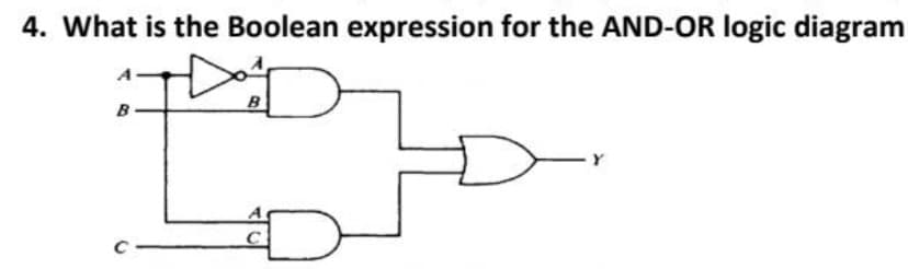
4. What is the Boolean expression for the AND-OR logic diagram B B


Q: A transmitter supplies 8 kW to the antenna when unmodulated. (a) What is the total power radiated…
A: Given: Unmodulated transmitter power is given as PC=8 kW Required: Total power radiated when…
Q: A T-junction power divider is the simplest network that can be used for power division or power…
A:
Q: What is tungsten,CFL,led bulb... Which one save electricity and why
A: The endeavour to lower energy consumption by utilising fewer energy services is known as energy…
Q: 1. Determine the RMS values of voltage and current, and the total power absorbed by the circuit…
A: In this question, two signals are given in harmonic form. We need to determine the rms value of…
Q: Explain each of the following terms. I. PDF and CDF II. LBP/CLBP
A: We have to describe term PDF and CDF (It is used in Atomic Engineering) LBP and CLBP (this is not…
Q: Find R3 (in 22) for a balanced bridge circuit if R1=18.60, R2=230, R4=13.6 0. (Give the answer in 1…
A: Given, R1=18.6Ω R2=23Ω R4=13.6Ω We need to Find here Resistance value R3
Q: Multiply out and factor: (A + B)(A' + E) = Type your answer with no spaces.
A: Given Boolean expression, F=A+BA'+E
Q: The magnetic field intensity in free space is given as H = Ho sine ay A/m. where 0 = (wt-Bz) and ß…
A:
Q: Suppose, that in an attempt to increase range, cordless telephone manu- facturers double the power…
A: Cordless telephones communicates using high frequency bandwidth that are allocated for this use. The…
Q: 15-10. Determine the effective radiated power for an antenna with directivity = 400 efficiency…
A: It is given that: D=400η=0.60Pin=50 W
Q: A 200kVA transformer with impedance of 5% and the power factor of the load is 85%. The primary…
A: Given data, Rating of transformer S = 2000 KVA Percent impedance %Z=5 % Power factor cosϕ=85 % =…
Q: 3. Based on Figure 1, determine which one is f and f'. Provide a reason for your choice. AAA Figure…
A:
Q: 4. Which of the following is the correct relationship between temperature (T) and mobility (u) of…
A: The correct option along with the explanation is provided in the following section.
Q: 3. Simplify the block diagram below. Then, obtain the closed-loop transfer function C/R. R S+1 S S+2…
A:
Q: Consider a continuous-time signal like the given picture with a frequency of 100 Hz. cos(x) V f. a.…
A: According to the question, for the given cosine signal as shown below We need to find (a) The…
Q: QI. Power and Power Factor Correction A factory has the following five major loads: Load 1: A motor…
A:
Q: QUESTION: Find the equivalent capacitor and the charge on eachcapacitor. 9V 6µF. 12V 3µF Find the…
A:
Q: Is it more efficient if the transient response is high or is it more efficient if the transient…
A: In general systems, we require the response to any change in the voltage to be faster, hence the…
Q: The instruction "BTG 0x89,3,1" takes. instruction cycles to execute. If the default RC oscillator…
A: Given data: Instruction is BTG 0×89,3,1 RC oscillator with TOSC=32 μs.
Q: (e) Determine the voltage in the circuit. 12 V 10 V 8V
A: Given circuit:
Q: Explain how a timing circuit works and list some applications.
A: Timing circuit : Timing circuit is a electronic circuit which synchronize any signal with the help…
Q: Determine Vout. +30 V OV -30 V Vin www 2.2 ΚΩ v 12 V t Vout
A:
Q: 52 Suppose an AC input of 100V is supplied, what is the voltage output of the given circuit below.…
A:
Q: Using Mesh analysis, find i3 in Amperes if Is = 2.44 A and R = 4.4 Ohms. Give answer in 3 decimal…
A: Given: Circuit diagram:
Q: Consider 15 Hz and 25 Hz are two different harmonic frequencies sinusoidal waves. a. Calculate the…
A: It is given that: f1=15 Hzf2=25 Hz
Q: For non-inverting amplifier as show in Fig. 1.26. Input voltage is 1 V and output voltage is 10 V…
A:
Q: In the circuit of Fig. P. 9.5.4 if the load is 2 kW, 230 V heater and V₂ = 230 V, 50 Hz. Calculate:…
A:
Q: 5. When a power Pt is transmitted by an antenna, amount of energy incident on the target is given by…
A: here we have to find the amount of energy incident on the target when a power Pt is transmitted by…
Q: For the 3 phase full wave ac voltage controller of Fig. P. 9.7.1 with a load resistance of R = 52…
A:
Q: 19. Consider the circuit present on the right. Assume all emfs are ideal batteries. B a) What is the…
A: The given circuit diagram is shown below:
Q: Two uniform spherical charge distributions (see figure below) each have a total charge of 28.1 mC…
A: Given data,
Q: Question No.17 If the slip in an induction motor is 0.25 and the synchronous speed is 600 rpm, the…
A: Given an induction motor with, Slip, s = 0.25 Synchronous speed, Ns=600 rpm
Q: For the below circuit what will be the time constant? ww t=0 9 V 8 Ω 3 μF
A: Given circuit,
Q: withstand 1425 kV peak lightning, 1050 kV peak switching and 480 kV peak pow frequency overvoltages.…
A: Solution- i) Classification of electrical clearance distances for the conductor to tower structure-…
Q: 5. Solve for V(s) and then v(t) (using a partial fraction expansion). Find v(t=o) and v(t-infinity).…
A: If we want to transform the function from complex domain or Laplace domain to time domain, we need…
Q: The total charge of a uniform insulating sphere is 14.16 nanocoulombs. If the radius of the…
A: The total electric flux, according to Gauss's law, is equal to the contained charge divided by the…
Q: Task 2: Consider the electrical system in the figure below, derive a differential equation that…
A:
Q: 9. Which of the following equation represents mass semiconductors in electronic circuits? action law…
A:
Q: Determine the voltage and current meter indications in each circuit.
A:
Q: 3. The radar in which both transmission and reception is done using the same antenna are called: a)…
A: The correct option along with the explanation is provided in the following section.
Q: 4. This is a phasor problem. Start by writing a current divider formula for I. Simplify and find…
A:
Q: TABLE 9-2.2 Total Resistance RT and Percentage of Error
A: The total resistance of the parallel resistance network can be reduced into single equivalent…
Q: 1. In the below circuit, find the current /through 1 Ohm resistor using Thevenin’s and Norton's…
A: Note: As per the policy we can solve only one question, please re-upload the remaining question as a…
Q: 3. The radar in which both transmission and reception is done using the same antenna are called:
A: The correct option along with the explanation is provided in the following section.
Q: Why transformer rated in KVA ?
A: Power may be transferred between two sides of a circuit using transformers without affecting the…
Q: m(t)=Amsen(comt) Figura 1 MODULADOR AM (DSB-LC) Vsalida(t) vc(t)=Acsen(wet)
A:
Q: The internal resistance of a primary cell is 412. It generates a current of 0.2A in an external…
A:
Q: values R = 3 × 10⁶ Q e applied voltage is ltage response v(t).
A:
Q: s[k] h x[k] n[k] r[k] W g[k] Decision Device u[k] = s[k-d] 1. Figure 1 above is schematic…
A: Two possible usage for that block So we have to understand followings points...
Q: Determine Vout in V. +10 V Vin OV- -10 V THE F 8 3V Vout when Vin = +10V = Vout when Vin = -10V =…
A: We can analyze that the given circuit is clipper circuit in positive half cycle and negative half…

Step by step
Solved in 2 steps with 2 images


- 2.Draw the logic diagram for the given Boolean equation using only NOR gates. Use as few gates as possible. F=A’B’+CD Write the question in copy and write in details it will be benefit for me thank youa) Write the output expression of the logic circuit shown in the figure. b) Minimize the expression using Boolean laws and theorems. c) Implement the minimized expression using 2 input NOR gates only.Create a logic diagram out of this boolean expression. CD+BD+BC+AD+AC+AB Note: All inputs A B C and D must be together.
- Write the Boolean expression that represents the combinational circuit, write the logic table and simplify the following using SOP. Please show complete solution. Thank you!Binary Subtractors 1. What are binary subtractors? 2. How does it work? 3. Types of binary subtractors. 4. Draw the logic circuit diagram. 5. Show the truth table. (Our subject is logic circuit and switching theory, and our lesson is combination logic circuit)Create a logic diagram out of this boolean expression. B'D+C'D+AB'+BCD' Note: All inputs A B C and D must be together.
- Provide a truth table, an output boolean expression (format your choice) and a logic circuit diagram. Cheers thanks mate. See sample in 2nd picUsing the Simplified Boolean function, create the logic diagram using NOR gates only. Determine the number of gates used. (ex. 2 gates)1. For a Half Subtractor, write () the truth table, (1) logic expressions, and (f) draw the circuit using logic gates: