4.4) The design shear strength D,V, is A) 81.1 kips B) 482 kips C) 529 kips D) 567 kips
Q: Solve for Shear the and moment diagram P CS Scanned with CamScanner 10 kN/m reactions and draw the…
A:
Q: Problem 5. Determine the moment of inertia with respect to 101 beniup91 9 to abutingom srit TY di aɛ…
A:
Q: | Refer to a robot shown. If P = 360 kN Which of the following most nearly gives the moment at point…
A:
Q: Show Attempt History Current Attempt in Progress A submarine is modeled as a cylinder with a length…
A:
Q: A solid cylindrical pine (S = 0.50) spar buoy has a cylindrical lead (S = 11.3) weight attached, as…
A: Required : Submerged Depth of the spar bouy, d
Q: Problem- An aluminium alloy (density 2600 kg/m³) casting is to be produced. A cylindrical hole of…
A: Given data- The density of aluminum- ρAl=2600 kg/m3, The density of sand core- ρcore=1600 kg/m3,…
Q: A cantilever beam with rectangular cross section is loaded as shown in figure. Plot the maximum…
A: Given- A cantilever Beam with rectangular cross-section carrying point load at free end. Required-…
Q: The flow of glycerine (kinematic viscosity V = 5 x 10⁴ m²/s) in an open channel is to be modeled in…
A:
Q: A river reach of 2.0 km long with maximum flood discharge of 10000 m³/s is to be physically modeled…
A:
Q: 4. Find the minimum weight of a man that can be supported by the wood if it has a total area of 1…
A:
Q: Determine the correct length of a line 256.32 m long measured using a 50 m steel tape at 30°C. The…
A: Given data Length of measured line (L) = 256.32 m Length of steel tape (l) = 50m Temperature at…
Q: A solid cylindrical pine (S = 0.50) spar buoy has a cylindrical lead (S = 11.3) weight attached, as…
A:
Q: What are the reactions at support A and C? Moment of point B? Shear at point B?
A: Shear force is the sum of all the forces on either left or right side of the section of the beam.…
Q: Trigonometry Review
A: Trigonometry review
Q: nd diameter
A: given data, length, l = 12 in diameter, d = 6 in compressive load, P = 150kips modulus of…
Q: Q- Water flows through a pipe having an inner radius of 10 mm at the rate of 36 kg/hr at 25° C. The…
A: given- inner radius R=10 mm=0.01 m, m=36 kg/hr=0.01 kg/s,density =1000 kg/m3,μ=0.001 kg/m.s,
Q: 4. A 54 kg girl is walking up a 22kg uniform beam. The coefficient of friction is 0.2 at all…
A:
Q: Problem 1.8 - Express the 260-N force in terms of components and parallel to the inclined plane…
A: As multiple questions are asked and as per the guideline only very first question will be…
Q: STATICS For the assembly shown below, the beam AB weighing 100 lbs is loaded with force P = 200 lbs.…
A:
Q: Determine e as a function of Gs, yd, Yw. + [Select] [Select] [Select] 1 + 47
A: *Multiple questions* As per our guidelines we are supposed to answer?️ only one question. Kindly…
Q: A retaining wall with measurements 30 mx 12 mx 6 m was constructed with bricks of dimensions 8cm ×…
A: Given data- Retaining wall size- 30 m×12 m×6 m, Brick size- 8 cm×6 cm×6 cm, 60% of the walls have…
Q: Write shear and bending moment equation and draw it for beam shown in Eigure (1). FINAL A mane 300…
A: Given data Write shear and bending moment equation and draw it for beam.
Q: Determine the reactions at the supports A and B of the compound beam. There is a pin at C. A - 6 m 2…
A:
Q: Derive an expression for the maximum value of deflection for the simlply supported beam.
A:
Q: Determine the correct length of a line 256.32 m long measured using a 50 m steel tape at30°C. The…
A:
Q: The long ranger is riding through a sandstorm. Does his mask (a bandanna that covers his nose)…
A:
Q: An open rectangular tank mounted on a truck has the following dimensions: L = 6 m, W = 3 m, H =…
A: As per bartleby guideline we are advised to solve top 3 question
Q: A 50-m steel tape was used to measure a line and the initial pull = 5.5 kg. Pull at time of…
A: There are various correction to be applied in case of surveying done by tape or chain. In the…
Q: oordinates and moment of inertia about x & y-ax he value of b=4 in.
A: centroid = x,y=∑Ax∑A, ∑Ay∑A parallel axis theorem, Ioo = Ixx + A(distance between the axes)2 Ioo =…
Q: SITUATION G. If the center of gravity of a ship in the upright position is 10 m above the center of…
A: Given data : At upright position Ship is 10 m above CG Displacement = 1000 metric tons. Angle = 30…
Q: 2. Members KL, CK, and CD ASS E 2m L 15 KN B 2m C 2m 2m 10 kN 2m F H 2m 4m
A:
Q: Complete solutions. Show free body diagrams. A long zipline carries two cable cars with a combined…
A: find the i.Mass of cable car X (kg) ii.Mass of cable car Y (kg) iii.Tension in cable AB (KN) iv.…
Q: Calculate the effective area of tensile strength of a tension member 180 × 65 × 8 mm. When it is…
A: Given: Unequal angle section: 180 x 65 x 8 mm Ag = 1896 mm2 Longer leg x=11.816 mm Shorter leg…
Q: During a series of tape measurements of a line, following values were determined: 887.57 m, 887.42…
A:
Q: The head loss for a laminar incompressible flow through a horizontal circular pipe is h₁. Pipe…
A: Given- Laminar In-compressible flow- Horizontal circular pipe. Head loss=h1,Length of…
Q: Determine the force in members bd, be,de & gh of truss shown in figure 3m 4m f 4m 400 KN #1 d + 4m b…
A:
Q: The characteristic compressive strength of concrete required in a project is 25 MPa and the standard…
A: Given- fck=25 MPa,standard deviation σ=4 MPa, It is needed to find the water cement ratio.
Q: hat do you think will be the use of computers in engineering in general and in Civil Engineering in…
A: solution of above problem is below:
Q: BkN C KN Y KN e the force in each member of the truss. Assume all
A: degree of static indeterminacy, Ds = m+ r -2j m = total number of members r = total number of…
Q: The mass center G of the 1505-kg rear-engine car is located as shown in the figure. Determine the…
A: Given data, Mass = 1505 Kg Assumption :- Take it as a force diagram. We have to apply…
Q: A transmission tower is held by three guy wires attached to a pin at A and anchored by bolts at B,…
A: Given TAB= 110 lb
Q: A simple frame is loaded and supported by a pin at A and a roller at B as shown in the Figure 2. The…
A:
Q: Determine the reactions at the supports of the beam loaded as shown below:
A: Answer Let us first draw free body diagram by resolving inclined forces into their components as…
Q: 1. A symmetrical parabolic pass through a point of the intersection is 197m 1). Determine the length…
A:
Q: How can you say that a structure can withstand the loads applied on it?
A: Everything that has mass/wight has be drawn towards the center of earth. This phenomena is due to…
Q: The flanged steel cantilever beam with riveted bracket is subjected to the couple and two forces…
A: To find out the equivalent couple moment and resultant R at A.
Q: Prove that the trusses shown are statically determinate and solve for the force members required for…
A: To find force in member KL,CL,BC,DK
Q: 2.2m 550N/m
A: Given E= 15 Gpa I= 50 ×106 mm4
Q: 6. A force P of magnitude 330 lb acts on the frame shown at point E. (a) Determine the rectangular…
A:
Q: 900N/m 1.1m 1.3m + 750N/m 1.1m
A: Loading and dimensions are given There will be reactions and moments at 2 fixed supports Form…
please solve part 4.4
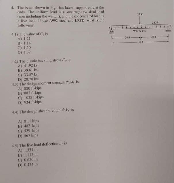
Step by step
Solved in 2 steps with 2 images
- For a beam subjected to a maximum bending moment of 100 kip-ft, design a A36 wide flanged section that will result in a factor of safety of 2 against yielding in normal stress. The emphasis is on the lowest weight section. The allowable shear stress of 24ksi is not exceeded. Question 3 of 4 Given your beam design, what is the ACTUAL maximum shear stress in the cross section? Vmax is 25 Kip 1.2 ksi 2.3 ksi 3.3 ksi 4.4 ksiA steel beam having a span “L” of 7 m is simply supported at its ends and is laterallyunrestrained over its whole length. It supports a uniformly distributed permanent action(dead load) (G) of 8 kN/m over its whole length, and a point load of 20 kN acting as an imposedaction (live load) (Q) at midspan.Design information: • Load combinations: Strength limit state: WL = 1.2G + 1.5QServiceability limit state: WS = G + Q• Maximum deflection under serviceability conditionsis not to exceed L/400• Effective length factors: kt = 1.0; kℓ = 1.4; kr = 1.0• Elastic modulus for steel Esteel = 200 GPa• Self-weight of the beam can be disregarded in all calculations(a) Sketch the load diagram showing the loads on the beam for the strength limit state, andcalculate the design moment (maximum bending moment) and the design shear force(maximum shear force)(b) Calculate the effective length (Le) of the beam from Le = kt×kℓ×kr×L and select from theTables provided the lightest suitable Universal Beam (UB)…Problem 1. A W30 x 116 beams has the top flange restrained against lateral displacement and rotation and has an unstiffened web. A point load is applied to the top flange at 2m. From the left support. The beam spans 12 m. Use A36 steel with yield strength of Fy = 248 Mpa. 1. Compute the maximum value of point load that may be applied without web crippling occurring. Properties of W30 x 116 d = 762 mm; K = 1.28 mm; bf = 266.7 mm; tf = 21.59 mm; tw = 14.33 mm
- For the structure shown in Figure, with a uniformly distributed service dead load wD= 1.5 kips/ft and a uniformly distributed service live load wL= 2 kips/ft applied to beam BC, answer the following questions: 1. Find the minimum area of steel required to serve as a cross section for member AB. Assume welded connections and shear lag factor U = 0.75 2. Find the lightest standard rolled W section to adequately resist the bending moments in beam BC. Assume that the top flange is laterally braced at points B, C, and at midspan. Compute the value of the bending coefficient cb.A WT305 x41 standard steel shape is used to support the loads shown. Assume W= 50 kN/m, LAB = 1.1 m. LEc-2.2 m, and LCD = 1.1 m. Consider the entire 4.4 m length of the beam and determine: (a) the maximum tensile bending stress at any location along the beam (enter a positive answer), and (b) the maximum compressive bending stress at any location along the beam (enter a negative answer)A compression member adopts a section of 530UB82.0 as shown in Fig. 1. Its steel grade is Grade 350. The effective lengths of the member are Lex=7.6 m and Ley=3.8 m. Determine the maximum design load of this compression member.
- A steel beam having a simple span of 8 m is subjected to a moment M at the left end (Clockwise) and 25% of M at the right end (Counter clockwise). It has no lateral support and has the following properties: bf = 210 mm rt = 53 mmd = 533 mm, Sx = 2.06 x 20^6 mm^3tf = 16 mm Fy = 248 MPa a) Determine the allowable bending stress.A single-span beam having unsupported length of 8m. has a cross section of 200mm x 350mm. (use nominal dimension). It carries a uniformly distributed load “W” kN/m throughout its span. Allowable bending stress is Fb=9.6 MPa and a modulus of elasticity of 13800 MPa. From the table, the effective length Le=1.92 Lu where Lu=unsupported length of beam. a. Compute the allowable bending stress with the size factor adjustment in MPA Round your answer to 3 decimal places. b. Compute the allowable bending stress with lateral stability adjustment in MPa Round your answer to 3 decimal places. c. Compute the safe uniform load “W” that the beam could carry in KN/m. (choose the smallest of prob. a and b.) use M=wl^2 / 8 Round your answer to 3 decimal places.A timber beam having a simple span of 6m carries a total load including its own weight of 15KN/m. It has a width of 250 mm and a depth of 300mm. Used dressed dimension by reducing its dimension by 10mm. The wooden section is made up of 80% Apitong.Fb = 16.5 MPaEw = 7310 MPaFv = 1.75Mpaa. Determine the maximum flexural stress of the beam.b. Determine the maximum shearing stress of the beam.c. Determine the maximum deflection of the beam.
- The beam in the figure carries a uniform load of 20 kN/m including its own weight, a concentrated load of 400 kN at 2.4 m from the left support and another concentrated load at 280 kNat 1.2 m from right end. The beam is laterally unsupported except at the two vertical ends. The beam is to be made of W 16 x 77. Use AISC Specifications for A36 steel Fy= 248.69 MPa. a. Determine the maximum bending moment of the beam. b. Determine the maximum or actual flexural stress of the beam. c. Determine the allowable flexural stress of the beam. d. Is it safe to use the said steel as beam? Why?A WT305 x 41 standard steel shape is used to support the loads shown. Assume w - 56kN/m, LAB - 1.0m, Lee - 2.0m, and Lco - 1.0m.Consider the entire 4.0 m length of the beam and determine:(a) the maximum tensile bending stress at any location along the beam (enter a positive answer), and(b) the maximum compressive bending stress at any location along the beam (enter a negative answer).The section of simply supported beam is HE450B, under distributed uniform dead load PG=20 kN/m and live load PQ=60 kN/m. Beam flange is laterally supported against compression from support and midpoint of the span. a. Determine safety of the section for bending (compare maximum beam moment with bending moment capacity of the section) b. Check section safety against shear Material is S235.