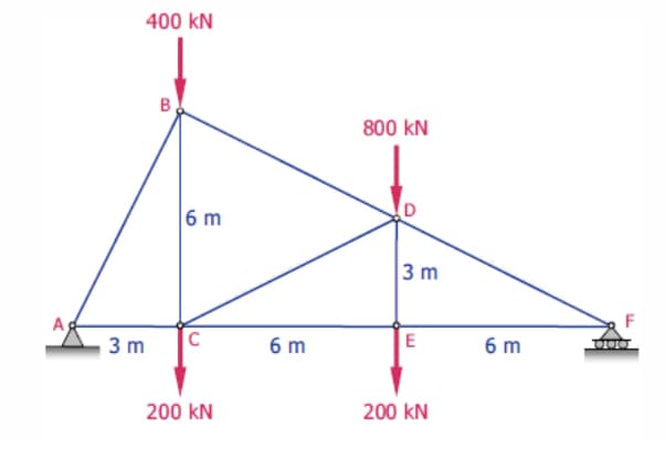
400 kN 800 kN 6 m D 3 m A 3 m 6 m E 6 m 200 kN 200 kN B.


Q: member HI; (b) maximum compression in member Cl; and (c) maximum tension in member CI. Also…
A: Given: P= 48000 lb which can be applied at any joint of the line FJ To determine: The location of P…
Q: 2- Compute the forces for members AB, BH and GH if P is 12kips. 4 m 3m 4 m 3m 4 m E 4 m 4m F H
A:
Q: Compute the forces in each members of the Howe Roof Truss shown. 30 30° 3 m C 30 30° 3 m 3 m 3 m 2.7…
A:
Q: For the frame and loading shown, determine the components of the forces acting on member CFE at C…
A: Drawing the FBD of the figure, Taking moment about D,
Q: 1- Using the method of joints, determine the force in members AB, AD and DE of the truss shown. 2500…
A:
Q: Determine the unknown forces by applying d’alemberts principle to a free body.
A: Even in the course of Fundamentals of Dynamics and Kinematics of machines, this principle helps in…
Q: A monosloped roof truss is loaded as shown. Determine the force in members CE, DE, and DF.
A:
Q: A monosloped roof truss is loaded as shown. Determine the force in members EG, GH, and HJ.
A:
Q: rent Attempt in Progress etermine the force in each member of the simple equilateral truss. The…
A:
Q: Determine all forces acting on member ACD of the The diameter of the pulley at D frame shown in Fig.…
A: Given data Weight of the body W = 500lb To determine the forces acting at ACD in the frame
Q: Calculate the forces in members BC, CF, and FG. D. 2 m A 42 kN 2 m B E 2 m F G 2 m 2 m
A:
Q: For the given loading, determine the zero-force members in the truss shown.
A: Zero force members are truss members which do not have tension or compression acting on them despite…
Q: 1. Find the maximum value of P that may be applied to the Fink Truss, if the maximum loads permitted…
A:
Q: 1- Determine the force in each member of the truss. State if the members are in tension or…
A:
Q: A Pratt roof truss is loaded as shown. Determine the force in members CE, DE, and DF. 3 kN 3 kN 3 kN…
A: Consider horizontally forward & vertically upward force as (+)ve and vertically downward force…
Q: Q1- Calculate the force in member CF of the truss. a) 5 KN (T)
A: Note:As per our guidelines we are supposed to answer only one question. Kindly repost other…
Q: Compute the force members of the given truss. T E 10 ft 10 k + 12. Force AD is a. 15k (C) 5 k ㅏ - 12…
A:
Q: Ex.13 The points B,C and D of the cantilever framework shown are attached to a vertical wall. The…
A:
Q: Compute the force in each member of the given truss. E 400 N
A:
Q: 20 kN 20 kN F -20 kN 3 m -40 kN E 3 m D 3 m -40 kN- 3 m B -3 m- 6 m -3 m-
A: Given: The magnitude of forces is 20 kN, 20 kN, 40 kN, and 40 kN.
Q: 1m 2m |c 10 kN 15 kN 4 - 2m panels = 8m 25 kN
A: Given:- To Find:- Forces in the members GF, GD, and CD using Method of Section
Q: Determine the force in member AC below given F1 = 4.6 kN and L2 = 3 m.
A:
Q: Calculate the forces in members (a) DE; (b) BE; and (c) BC. Indicate tension or compression. 4 m D.…
A:
Q: Q2) determine the zero-force members in the truss shown below. IS
A:
Q: 1200 lb C D A B 4 ft
A:
Q: Determine the force in member BF (in kN, round-off to 2 decimal places, include "-" if in…
A:
Q: 2. Determine the forces for the members of BC, BE and AE using the Section method.
A:
Q: Question-4 Find the magnitude and nature of the forces in members AC, AD, DB, CE, CF and FD by…
A: Given: The truss is shown below:
Q: Q2:Calculate the forces in members CG,GF and CF for the truss shown. 2 kN B 2m 4 kN
A:
Q: e force in each member of the truss shown.
A: To find Force in each member of the truss
Q: For the given loads w = 28 KN/m and M-70 KN.m is supported as shown by a roller at D and a hinge at…
A:
Q: The force in member CD of the given truss
A: given truss as shown below
Q: For the given loading, determine the zero-force members in the truss shown.
A:
Q: Calculate the forces in members CE, BC, and BE. Indicate if each force is COMPRESSION OR TENSION…
A: for the given truss To determine forces in member BC, BE and CE
Q: Find force in member KD
A:
Q: Calculate the forces in members AC, AD, and DE for the loaded truss. Restraining link BC is…
A:
Q: A 1 kN 2 m 2 kN 2 m 2 m 2 m 2.
A:
Q: Q: Calculate the forces in members CG and CF for the truss shown. 2 kN 2 m B 2m C 2 m 4 kN 3 m E
A:
Q: For the shown truss, the force in member CD equals
A: To find force in member CD
Q: alate the forces in members BC,BE and CE, of the loaded truss All triangles are isosceles 6 kN B 4 m…
A:
Q: Compute the forces Dy, Dx, Gy and AB, by using section method. 20KN 10 KN 10KN D 4m G E 0 6m A i B ↓…
A:
Q: Calculate the forces in members AB, BH, and BG. Members BF and CG are cables which can support…
A: GIVEN DATA - A PLANE TRUSS GIVEN WE HAVE TO FIND FORCES IN GIVEN MEMBER OF TRUSS
Q: Situation 2. Determine the member forces BD, CD, and CE using Method of Section. Indicate if (T) or…
A: For the given truss To determine member force in BD,CD, and CE
Q: A monosloped roof truss is loaded as shown. Determine the force in members CE, DE, and DF.
A: Moment acting about point A is…
Q: From the given trusses below, determine the force in the member FG. (kN)
A: Given data Given truss system
Q: 4/4 Calculate the forces in members BE and BD of the loaded truss. B C 8 8' A 8' E D 1000 lb
A: Method of joints is the easiest way to determine the unknown forces in the truss structure. Step 1:…
Q: Determine the forces in members C
A: Given data given truss system
Q: 1. Determine the force in members CD, CJ, and KJ and state 6 kN if these members are in tension or…
A:
Q: Calculate the forces in members AB, BG, and GF using the method of section.
A: Given data: F=6 kN Need to determine the forces in members AB, BG, and GF using the method of…

Step by step
Solved in 3 steps with 3 images

- What steps should be taken to obtain The resultant internal loadings at a point located on the section of a body using the method of sections?Please help :( given: T(sub B) = 80.11, T = 5.67 kN-mA solid circular shaft is acted upon by thetorques as shown. If G= 12, 000 ksi determine:a. Rotation of wheel D with respect to A.b. Shear stress at point EDiameter of shaft:A-B = 2inC-D = 2inB-C = 4inT1 = 2.5 π in.kipsT2 = 8.5 π in.kipsT3 = 7 π in.kipsT4 = π in.kips
- STRENGTH OF MATERIALS. Please show the complete solutions. Rate will be given. Answer in 3 decimal places! The steel shaft DF consists of three concentric tubes and is supported by smooth bearings at D and E. It is coupled to a motor at F, which delivers 14 kW of power to the shaft while it is running at 52 rev/sec. The gears A, B, and C remove 3 kW, 5 kW, and 6 kW, respectively. The shaft is free to turn in its support bearings D and F. Determine the shearing stress developed in segments BC and CE.The tubular drive shaft for the propeller of a hovercraft is 6 m long. If the motor delivers 4 MW of power to the shaft when the propellers rotate at 25 rad>s, determine the required inner diameter of the shaft if the outer diameter is 250 mm. What is the angle of twist of the shaft when it is operating? Take tallow = 90 MPa and G = 75 GPa.a: What is the magnitude of torque applied to the shaft? b: The magnitude of the Polar Moment of Inertia of the shaft cross-section? c: The magnitude of the shear stress at r=0in (center of shaft) is?
- The maximum torsional shear stress of a shaft with diameter D can be found at what distance from the center of the shaft?M = 1093.7 N-m M = 1511.8 N-m M = 1230.2 N-m M = 1161.6 N-m1. A steel shaft is subjected to the torques shown. The shaft is solid with a diameter of 1 in and G = 12,000 ksi. Determine: (a) internal torque (lb ft) in each segment. Include the necessary diagram to show these internal forces (b) maximum shear stress (psi) in each segment (c) rotation angle of pulley D w/r to the support of A. Follow the rule of signs given in the lecture. Include the necessary FBDs of sections.
- Determine the maximum bending stress in the brass. Determine the maximum bending stress in the steel. Determine the stress in the brass at the seam where the brass and steel are bonded together. Determine the stress in the steel at the seam where the brass and steel are bonded together.The steel shaft is formed by attaching a hollow shaft to a solid shaft. Determine the maximum torque T (in Nm) that can be applied to the ends of the shaft without exceeding a shear stress of 70034763 Pa and angle of twist of 2.23ᴼ. Use G = 83000000000 Pafor the shaft, x = 2.3 m, and y = 1.89 m. Round off the final answer to two decimal places.Please help me, I only have 30 mins left. TY!A shaft when subjected to pure torsion developed a stress of 50 Mpa. If polar moment of inertia is 6.1359 x 10 -7 m4 , determine the maximum torque the shaft could handle. A. 1.23 KN.m B. 1.68 KN.m C. 1.84 KN.m D. 2.48 KN.m