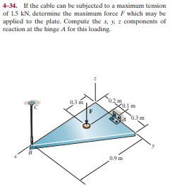
4-34. If the cable can be subjected to a maximum tension of 1.5 kN, determine the maximum force F which may be applied to the plate. Compute the x, y, z components of reaction at the hinge A for this loading. 0.3 m 02m X0.1 m 03m 0.9 m
Q: •5-21. Determine the horizontal and vertical components of reaction at the pin A and the tension…
A:
Q: 6-53 Determine the force exerted by the cable at B and the reaction at support A of the bar shown in…
A: Drawing the free body diagram of the system, T is the force in cable. Taking the moment about A,
Q: Determine the reaction at the roller support at point B in kN unit. Take P = 5.6 kN. P kN B 30° 6 m-…
A:
Q: 5-27. As an airplane's brakes are applied, the nose wheel exerts two forces on the end of the…
A:
Q: Q4 - Determine the reactions at the supports. 500 N/m www...... B 4 m 4 m 30
A:
Q: 3-40. The spring has a stiffness of k 800 N/m and an unstretched length of 200 mm. Determine the…
A:
Q: 4-22. As an airplane's brakes are applied, the nose wheel exerts two forces on the end of the…
A: → Consider the following , Free body diagram of the frame EC=400 tan 20°EC=145.588…
Q: 4-14. The post is made of Douglas fir and has a diameter of 60 mm. If it is subjected to the load of…
A:
Q: 3-31. If the bucket weighs 50 lb, determine the tension developed in each of the wires.
A:
Q: R4-1. If the roller at B can sustain a maximum load of 3 kN, determine the largest magnitude of each…
A: To find out F if max load taken by roller at B is 3KN
Q: *4-20. The 1500-N electrical transformer with center of gravity at G is supported by a pin at A and…
A: Draw the F.B.D of the given transformer.
Q: 4-59. The friction at sleeve A can provide a maximum resisting moment of 125 N m about the x axis…
A: Given Data M=125 N.m
Q: 4-38. The shaft is supported by three smooth journal bearings at A, B, and C. Determine the…
A: Draw the rough sketch of the Free Body Diagram for the above system of forces.
Q: 5-27. As an airplane's brakes are applied, the nose wheel exerts two forces on the end of the…
A: Given Two forces = 2 kN and 6 kN Find The reaction and Force
Q: If F=4 kN and P = 7 kN, compute the magnitude of the reactions at the fixed support at A. 15 kN.m 30…
A:
Q: *4-24. Determine the distance d for placement of the load P for equilibrium of the smooth bar when…
A: Taking Free body diagram of the bar, ∑Vertical forces = 0P-R×cos(θ)=0P=R×cos(θ)∑Moment about…
Q: 4-30. Determine the tension in cables BD and CD and the x, y, z components of reaction at the…
A: The load vector, The tension in cable BD,
Q: 4-30. The weight of the kentledge exerts an axial force of P = 1500 kN on the 300-mm diameter high…
A: Given:P=1500 Knd=300 mmL=12 mF=0
Q: 3-31. The springs on the rope assembly are originally stretched 1 ft when 0 = 0°. Determine the…
A:
Q: 5-42. If a force of F - 50 N acts on the rope, determine the cutting force on the smooth tree limb…
A:
Q: *4-36. The bar AB is supported by two smooth collars. At A the connection is a ball-and-socket joint…
A: Given:- According to the statementAt point A; ball and socket jointA→=Axi^+Ayj^+Azk^At point B;…
Q: P5-3. then draw the free-body diagrams of each member of the identify any two-force members, and…
A: If in an element no load or force is acting between the pins or hinge supports at both ends then…
Q: 3-31. The springs on the rope assembly are originally stretched 1 ft when e that must be applied so…
A:
Q: 4-59. The coefficient of static friction between the drum and brake bar is = 0.4. If the moment M =…
A:
Q: 4-17 If rope BC will fail when the tension becomes 50 kN, determine the greatest vertical load F…
A:
Q: F4-6. Determine the reactions at the smooth contact points A, B, and C on the bar. 250 N 307 015 m…
A: Given Applied load 250 N Structure To find Reaction at point A, B and C
Q: Q4 - Determine the reactions at the supports. 500 N/m www.com B - 4 m 4 m- 1.6 kN
A: To determine the reactions.
Q: 4-35. The uniform concrete slab has a mass of 2400 kg. Determine the tension in each of the three…
A: As given the slab is in equilibrium, the net moment on the slab will be zero,…
Q: 3-2. The members of a truss are pin connected at joint 0. Determine the magnitude of F, and its…
A:
Q: 5-34. Determine the horizontal and vertical components of reaction at the pin A and the normal force…
A:
Q: Determine the internal forces (V, F and M) in member BCD at K. Draw free body diagrams for portion…
A:
Q: R4-6. A vertical force of 400 N acts on the crankshaft. Determine the horizontal equilibrium force P…
A: Apply static equilibrium equation…
Q: The tapered shaft is confined by the fixed supports at A and B. If a torque T is applied at its…
A: Given data: The radius of the shaft at point A is 2c. The radius of the shaft at point B is c. The…
Q: Find the reactions at both supports A and E. Also determine the axial forces developed at member CF.…
A: Given figure To find : the reactions at both supports A and E. To determine: the axial forces…
Q: 4-23. If d - 1 m, and e- 30, determine the normal reaction at the smooth supports and the required…
A:
Q: 5. Determine the force subjected by F if the connection is fixed at 0 and radius R is 1 feet. 60_lb…
A:
Q: *4-36. If the load has a weight of 20 kN, determine thex, y, z components of reaction at the…
A: Given: Load has a weight of 20 KN showing the various forces acting on the given figure by free…
Q: *5-88. Determine the horizontal and vertical components of reaction at the pin A and the force in…
A: Given Force, F = 100 N Find Calculate the reactions and the force
Q: R4-3. Determine the normal reaction at the roller A and horizontal and vertical components at pin R…
A: Draw the free body diagram of the member as shown below. We need to find the normal reactions at…
Q: 4-74 For the frame shown, determine the magnitude of the pin reaction at B. Neglect the weight of…
A:
Q: Determine the angle (0), and the reaction forces located at A and H. Use the method of sections to…
A: As per our guidelines we are supposed to answer first three sub-parts. The diagram for angle is…
Q: 6-42 An angle bracket is loaded and supported as shown in Fig. and the reaction at support B.…
A: The free-body diagram of the given bracket can be drawn as shown below, Here T is the tension force…
Q: 4-3. Determine the reactions at the supports. S00 N/m
A: Given: To find The reactions at supports
Q: 4-15. The 10-kg uniform rod is pinned at end A. If it is subjected to a couple moment of 50 N-m,…
A: Given data: Mass of uniform rod = 10 kg Magnitude of couple applied = 50 N m…
Q: 5-41. Determine the resultant force at pins A, B, and C on the three-member frame. S00 N 200 N/m 2 m
A: Draw the free-body diagram AC Take the moment about A…
Q: *5-40. Determine the horizontal and vertical components of force which the pins at A and B exert on…
A: Consider the free body diagram of the member AED as shown below.
Q: 4-2. Determine the reactions at the supports 900 N/m 600 N/m -3 m 3 m.
A: Draw the free-body diagram of the beam.
Q: 4/93 Determine the magnitude of the pin reaction at A and the magnitude and direction of the force…
A:
Q: Both pulleys are fixed to the shaft and as the shaft turns with constant angular velocity, the power…
A: The schematic diagram of the shaft is as follows: Calculate the moment about x-direction as…
Trending now
This is a popular solution!
Step by step
Solved in 3 steps
- Find the force F that must be applied at the handle to produce a clamping force of 75 lbs at E, given:L1 = 8 in, L2 = 2.25 in, L3 = 1 in, L4 = 10 in, θ = 30 °in the pulley system and the diagram above, assume that the bearings at oh and C are properly aligned and smooth and that T2 =30 N all dimensions in millimeters and the belt tensions are all tangential to the pulleys a. If the shaft runs at a constant speed, determine the tension T1 b draw a free body diagram of the shaft and determine the reactions at bearing sea in terms of the components along the Y and Z axis. Assume neither bearing and oh or see produces an axial thrustW=25N, h=60mm. Find the spring force acting on the member DE and the reactions of the support at F.
- find the force in each tinder (ring) and determine if it is in tension or compression using the node method a) h= 0.1 m b) h= 0.5 mThe spring has a stiffness of 830 N/m and is undisturbed and measures 400 mm. Determine the forces on the BC and BD cables when the spring is stretched in the position shown in the figure.Both pulleys are fixed to the shaft and as the shaft turns with constant angular velocity, the power of pulley A is transmitted to pulley B. The bearings are in proper alignment and exert only force reactions on the shaft. Please note the positive direction of each axis. Determine the horizontal tension T in the belt on pulley B if θ=0∘. Determine the x, y, z components of reaction at the journal bearing C. Determine the x, y, z components of reaction at the thrust bearing D.
- The plate is made of steel having a density of 7850kg/m3. If the thickness of the plate is 10 mm,determine the horizontal and vertical components ofreaction at the pin A and the tension in cable BC.The bracket is held to the wall using three A-36 steel bolts at B, C, and D. Each bolt has a diameter of 0.5 in. and an unstretched length of 2 in. If a force of 800 lb is placed on the bracket as shown, determine the force developed in each bolt. For the calculation, assume that the bolts carry no shear; rather, the vertical force of 800 lb is supported by the toe at A. Also, assume that the wall and bracket are rigid. A greatly exaggerated deformation of the bolts is shown.Determine the support reactions at the smooth collar A and the normal reaction at the roller support B.
- The post is made of Douglas fir and has a diameter of 100 mm. If it is subjected to the load of 20 kN and the soil provides a frictional resistance that is distributed along its length and varies linearly from w = 4 kN>m at y = 0 to w = 12 kN>m at y = 2 m, determine the force F at its bottom needed for equilibrium. Also, what is the displacement of the top of the post A with respect to its bottom B? Neglect the weight of the post.The railcar docklight is supported by the 1 8-in.-diameter pin at A. If the lamp weighs 4 lb, and the extension arm AB has a weight of 0.5 lb>ft, determine the average shear stress in the pin needed to support the lamp. Hint: The shear force in the pin is caused by the couple moment required for equilibrium at A.If the roller at A and the pin at B can support a load up to 4 kN and 8 kN,respectively, then determine the maximum intensity of the distributed load w, measured in kN/m,so that failure of the supports does not occur. Note that the roller support at A has an inclined axisby which the reactionary force will act through.