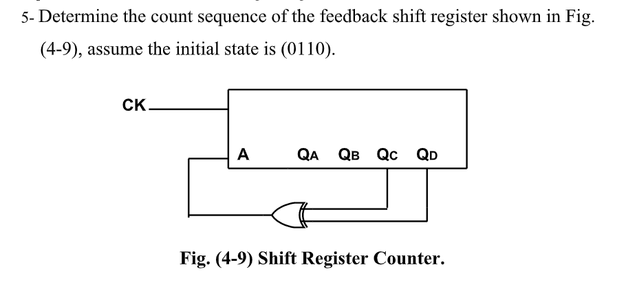
5- Determine the count sequence of the feedback shift register shown in Fig. (4-9), assume the initial state is (0110). CK. A QA QB Qc QD Fig. (4-9) Shift Register Counter.


Q: An A/D converter uses 14-bit numbers and has a voltage range between +6V to -6V. a. What…
A:
Q: Design a counter circuit that has 2 inputs (X and Y), and 2 outputs (W and Z) by using both “binary”…
A: The state table for the given logic is shown below:
Q: Consider a derivative integral controller (PID), it is necessary to determine the value of k (gain)…
A: Given block diagram is - Given that difference between output and input (Steady state error) is…
Q: Consider an 8-bit linear feedback shift register (LFSR) with the feedback function: B7 EXOR B4 EXOR…
A:
Q: B) What are the characteristics of an instrument amplifier? C) What are the advantages of…
A: Instrumentation Amplifier : An instrumentation amplifier is a differential amplifier containing…
Q: For the following root locus plot of the second-order process G(s) where two open-loop poles are…
A:
Q: 4(B) The lower cutoff frequency of first stage of the amplifier is 100 Hz and that of second stage…
A: Given data: The lower cut-off frequency of stage 1: 100 Hz The lower cut-off frequency of stage 2:…
Q: Consider the simplified model of a DC Motor in unity feedback with a disturbance torque, W(s),…
A:
Q: Of the four circuits as shown (a) Which circuits use negative feedback to increase the output…
A:
Q: (a) If the overall transfer function for motor control system in Figure Q3 (a), is 40 rpm / V. What…
A: The overall transfer function for motor control system is 40 rpm/V. We need to determine the…
Q: Q3: For the Digital-to-Analog converter circuit shown in Fig. 1, if the LOW state voltage is 0 Volt,…
A:
Q: K(s² +2) Q1: Sketch the root locus for the unity feedback system with G(s) = (s+3)(s+4) Given the…
A:
Q: Q1)information signal is PCM using 8 levels quantization if the signal is given as cos(4t with…
A: Sampling is the reduction of continuous time signal to discrete time signal . Analog signal are…
Q: (A) In a 6-bit weighted resistor DAC in which the feedback resistor Rf has 4times the value of MSB…
A:
Q: . Why is it that lower frequencies are not practically possible in the case of Harley os . Which…
A: In this question we will write Hartley oscillator related problems....
Q: Determine the values of the gain K and the feedback constants Kh of the system shown so that the…
A:
Q: Consider the differential amplifier shown using Darlington pairs, and assume that all transistors…
A: Given: Consider the differential amplifier shown using Darlington pairs, and assume that all…
Q: Question 3 rit) e(t) y(t) Gfs) Gals) a) Find the characteristic equation of above closed-loop…
A:
Q: 5- Determine the count sequence of the feedback shift register shown in Fig. (3), assume the initial…
A:
Q: Suppose we have a sensor, with a Thévenin resistance that varies from zero to 10 kΩ connected to the…
A: The described amplifier circuit is given in the diagram below. First let’s start from output circuit…
Q: نقطتان )2( Q) In the negative feedback, * :which statement is true (a) The gain with the feedback is…
A:
Q: (A) In a 4-bit weighted resistor DAC in which the feedback resistor Rf has 5 times the value of MSB…
A: Note: We are authorized to answer one question at a time since you have not mentioned which question…
Q: . Sketch the Root Locus for the unity feedback system in Fig. 3. Show the followings: a) axis…
A: Root Locus is the Locus of closed loop poles by varying the gain from 0 to infinity. Break away and…
Q: A unity feedback system has the characteristic equation shown below. Use the Routh - Hurwitz…
A:
Q: Which loop structure always executes at least once? for do-while while O if
A: In do-while loop structure, the condition is check at last. So even if the condition do not satisfy…
Q: Please find the following: (a) The error constants Kp, Kv and Ka and also the system type. (b) The…
A: Note: Since you have posted a question with multiple subparts, we will solve the first three…
Q: Which one of the following statement is correct for positive feedback? Select on
A:
Q: What is the outpul voltage from a 4-bit R-2R DAC, if the feedback resistor is 10 kQ and the network…
A:
Q: O1: Consider the control system whose signal flow graph is shown below. Determine the system trans…
A:
Q: A second order stable under-damped LTI system is placed in a unit feedback loop with a proportional…
A: When a second order stable under damped LTI system is placed in a unit feedback loop with a…
Q: Q1)information signal is PCM using 8 levels quantization if the signal is given as cos(4t) with…
A: According to the question, An information signal is PCM using 8 level quantization if the signal is…
Q: Consider the following statements: 1-The effect of feedback is to reduce system error. 2-Feedback…
A:
Q: Without writing or drawing tools to lean on, you must use words, not equations, graphs or schematics…
A: Differential amplifier As state by the name it is a electronic circuit which is used for…
Q: A process furnace heats a process stream from near ambient temperature to a desired temperature of…
A: We are authorized to answer three subparts at a time since you have not mentioned which part you are…
Q: Consider the circuits as shown. (a) Which circuits use negative feedback to decrease the input…
A: The circuits which are using negative feedback to decrease the input resistances are: (a) and (d)…
Q: Answer the questions about the Binary Weighted DAC: i. Design a 6-bit Binary Weighted Resistor DAC…
A:
Q: B-Consider the ideal Current - Shunt feedback amplifier. Assume that the source resistance is Rs =0.…
A:
Q: of an operational amplifier are 1000 and 100000, The differential gain and common mode rejection…
A: We know that: Putting this in formula of:
Q: Using the Routh-Hurwitz criterion and the unity feedback system below, with K G(s): s(s + 1)(s +…
A: Given that G(s) = k/ s(s+ 1)(s + 2)(s + 5)
Q: Q2: For the Digital-to-Analog converter circuit shown in Fig. 1, if the LOW state voltage is 0 Volt,…
A: The given circuit diagram is shown below: It is given that: R1=3 KΩR2=6 KΩR3=12 KΩR4=24 KΩR5=3 KΩ
Q: Please can you explain the theory of operational
A: Op-Amp is an integrated circuit that can amplify both AC and DC weak electrical signals.
Q: One of the disadvantage of negative feedback loop is lag caused because it can only be exerted after…
A: The negative feed back has so many advantages such as simple in design ,less cost and high…
Q: 3. For the unity feedback systems K(s² + 6s + 6) G(s) : (s+ 5)2(s + 3) a. Find the system type b.…
A: We need to tell about type and error for given input signal .
Q: 3. Consider the system a) Use state feedback ? = ?? to assign the eigenvalues of ? + ?? at −0.5 ±…
A: The system equation is: x=0110x+0-1u,y=10x· (a). We need to find the state-feedback control law such…
Q: Consider the block diagram shown below. 100 Ys) Pisitioa Rs) Ks Velocity Position feedback State…
A:
Q: (a) A Differential amplifier has collector resistances Re1 = Rc2 = 5.1KN. and Vcc = 15V. The…
A:
Q: Qs: Calculate the voltage gain with and without feedback for the following circuit and determine the…
A: First we will find out Gain without feedback then we will find out Millar input and output impedance…
Q: Question 4 a) Derive an expression for the close loop gain of an amplifier if negative feedback is…
A: Solution :- Part a:- Block diagram of negative feedback system is shown in above figure:- A =…
Q: Determine the value of K, for which the inner loop will have two equal negative real poles. Where…
A: The given question has multiple parts. Since you have not mentioned which part you are looking for,…
Q: K(s² +2) Q1: Sketch the root locus for the unity feedback system with G(s)= (s +3)(s+4) Given the…
A:


Trending now
This is a popular solution!

Step by step
Solved in 2 steps with 1 images


- Consider an 8-bit linear feedback shift register (LFSR) with the feedback function: B7 EXOR B4 EXOR B0 and register bits (B7, …, B0). In each cycle the register content is shifted to the right (with B7 replaced by the feedback function output, and B0 shifted out). Convert the 2 rightmost digits of your student id into 8-bit binary and use this value as initialisation vector for your LFSR. From there on calculate the output of the first 6 LFSR cycles, i.e. the first 6 stream bits being produced. Example: 1001569 → 6910 = 010001012 ID = 19205860below is the representation of a linear control system in the state space.a) examine the controllability and observability of this systemb) estimate the unit digit response by finding the current eigenvalues of this systemC) find the feedback Matrix K= (k1 k2) that must be applied so that the system can be a two - layer root in-2are given a system’s transfer function as T(s) = 21 Construct a state-space model for the given system using ” Observer Canonical Form” method. | that the full state information of this system is available, design a state-feedback controller for this put the desired closed loop poles at ~2+ 2. Now, assume that the state information of the system are measurable, for this case what kind of controller do you suggest? Design this controller so that the ¢ Joop poles of the system are located at —10 + 510.
- The classic feedback amplifier as shown has β =0.125. What are the loop gain T, ideal closedloop gain AIdeal v , actual closed-loop gain Av, and the fractional gain error FGE if (a) A =∞? (b) A =84 dB? (c) A =20?When a unit ramp input is applied to the unity feedback system having closed loop transfer function, C(s)/R(s)= Ks+b/s2+as+b , (a>0, b>0, K>0), the steady state error will be ?below is the representation of a linear control system in the state space.a) estimate the unit digit response by finding the current eigenvalues of this systemb) find the feedback Matrix K= (k1 k2) that must be applied so that the system can be a two - layer root in-2
- Without writing or drawing tools to lean on, you must use words, not equations, graphs or schematics in your explanation. The current in a differential pair of transistors swings between the two sides of the transistor pair as the input voltage swings between the inputs. The output voltages of course follow the current inversely. Is this swing of current related to one of the chief advantages of differential operation, the elimination of common mode signals? Keep in mind, there is a restricted range of allowed current (and voltage) swing to keep the amplifier operating in a linear wayA. If the forward gain is 5 and feedback gain is 1, determine the close-loop gain of a negative feedback amplifier. answer: B. For a Wien-bridge oscillator (as presented in the lecture), if the feedback resistor has a value of 10-kohm, determine the value of Ri (in kilo-ohm). answer:1. During the process of digital sampling, data can be lost due to aliasing.Analyse this problem and provide at least two possible solutions. Also,determine the rate at which a signal should be sampled, if the highestfrequency is 50MHz. (b) An 9-bit binary number is used to represent an analog value in the rangefrom -10oC to 100oC, determine the resolution of the system andinterprete your result.
- This mode of control is not recommended for disturbances that are erratic and noisy in nature. a. integral b. on/off c. proportional d. derivative What is calculated as the error in a negative feedback loop? difference between measured variable and load difference between load and set point difference between load and process output 4. difference beween measured variable and set point A proportional controller whose gain has a very large value approaches which mode of control? on/off proportional-derivative proportional-integral proportional-integral-derivativeWhat is the range of values of the kp gain so that the output of the system in closed loop is, i) Overshocked, ii) Critically damped, iii) Undercushioned, iv) Without damping?For the system of Figure 2, ? = 2 s and?(?) =?(? + 0.8)(? − 1)(? − 0.6)Figure 2. Unity feedback system.a) Determine the range of ? for stability using the Routh–Hurwitz criterion.b) Determine the range of ? for stability using the Jury test. For more detailed question you can look at the image.