5. After the power supply leads are plugged in how would you measure the potential difference across each resistor? Explain. 6. How would you measure the current through the (green, brown, brown, gold) resistor? Explain. 7. Is it possible to measure the current through the other two resistors? Explain.
5. After the power supply leads are plugged in how would you measure the potential difference across each resistor? Explain. 6. How would you measure the current through the (green, brown, brown, gold) resistor? Explain. 7. Is it possible to measure the current through the other two resistors? Explain.

Delmar's Standard Textbook Of Electricity
7th Edition
ISBN:9781337900348
Author:Stephen L. Herman
Publisher:Stephen L. Herman
Chapter25: Surge, Spike, And Lightning Protection
Section: Chapter Questions
Problem 10RQ: In reference to the load, how are capacitors connected to help prevent voltage spikes and surges?...

Related questions

Question
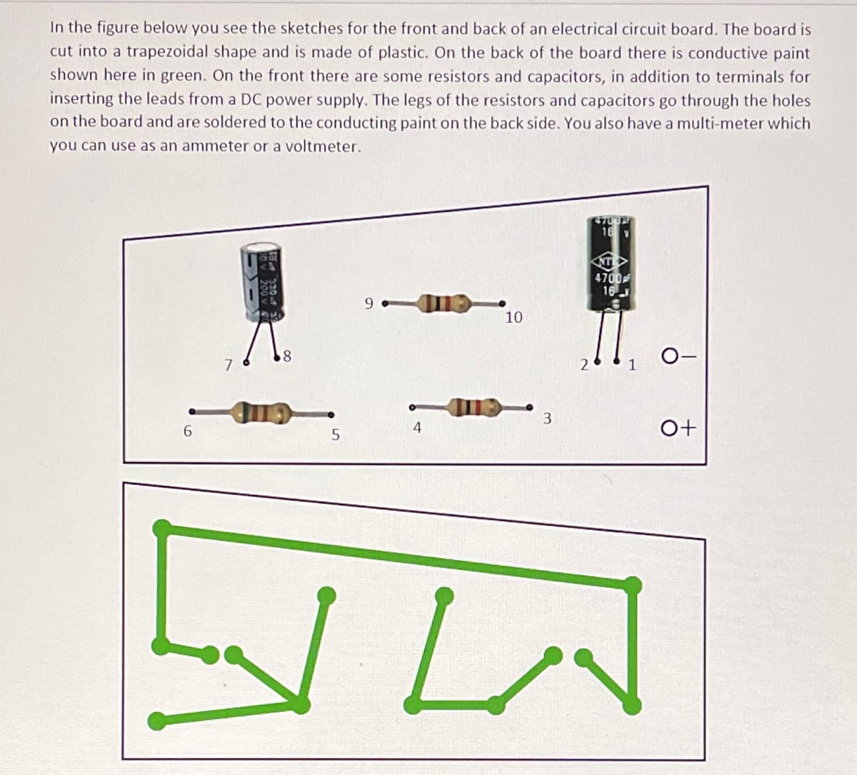
Transcribed Image Text:In the figure below you see the sketches for the front and back of an electrical circuit board. The board is
cut into a trapezoidal shape and is made of plastic. On the back of the board there is conductive paint
shown here in green. On the front there are some resistors and capacitors, in addition to terminals for
inserting the leads from a DC power supply. The legs of the resistors and capacitors go through the holes
on the board and are soldered to the conducting paint on the back side. You also have a multi-meter which
you can use as an ammeter or a voltmeter.
16 v
4700
16
10
8
O-
7
3.
6.
4
O+
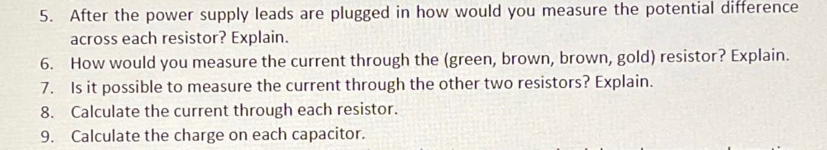
Transcribed Image Text:5. After the power supply leads are plugged in how would you measure the potential difference
across each resistor? Explain.
6. How would you measure the current through the (green, brown, brown, gold) resistor? Explain.
Is it possible to measure the current through the other two resistors? Explain.
8. Calculate the current through each resistor.
9. Calculate the charge on each capacitor.
7.
Expert Solution
This question has been solved!
Explore an expertly crafted, step-by-step solution for a thorough understanding of key concepts.

Step by step
Solved in 3 steps with 2 images

Knowledge Booster


Learn more about
Need a deep-dive on the concept behind this application? Look no further. Learn more about this topic, electrical-engineering and related others by exploring similar questions and additional content below.Recommended textbooks for you
Delmar's Standard Textbook Of Electricity
Electrical Engineering
ISBN:
9781337900348
Author:
Stephen L. Herman
Publisher:
Cengage Learning
Delmar's Standard Textbook Of Electricity
Electrical Engineering
ISBN:
9781337900348
Author:
Stephen L. Herman
Publisher:
Cengage Learning