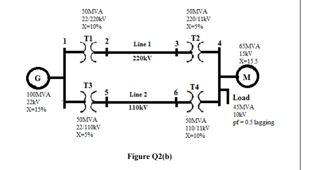
50MVA 22/220KV X=10% SOMVA 220/11kV X-5% T1 T2 Line 1 65MVA 15kV 220kV X-15.5 M T3 T4 100MVA Line 2 Load 22kV 110kV 45MVA X-15% 10kV SOMVA SOMVA 22/110kV pf = 0.5 lagging 110/11kV X-10% X-5% Figure Q2(b)
50MVA 22/220KV X=10% SOMVA 220/11kV X-5% T1 T2 Line 1 65MVA 15kV 220kV X-15.5 M T3 T4 100MVA Line 2 Load 22kV 110kV 45MVA X-15% 10kV SOMVA SOMVA 22/110kV pf = 0.5 lagging 110/11kV X-10% X-5% Figure Q2(b)

Power System Analysis and Design (MindTap Course List)
6th Edition
ISBN:9781305632134
Author:J. Duncan Glover, Thomas Overbye, Mulukutla S. Sarma
Publisher:J. Duncan Glover, Thomas Overbye, Mulukutla S. Sarma
Chapter3: Power Transformers
Section: Chapter Questions
Problem 3.41P: Consider the single-line diagram of the power system shown in Figure 3.38. Equipment ratings are...

Related questions
Question
Transcribed Image Text:50MVA
50MVA
22/220KV
220/11kV
X=10%
X-5%
TI 2
T2
3
Line 1
65MVA
15kV
220kV
X-15.5
M
T3
T4
100MVA
Line 2
Load
22kV
X=15%
110kV
45MVA
10kV
50MVA
50MVA
pf = 0.5 lagging
22/110KV
110/11kV
X-5%
X-10%
Figure Q2(b)
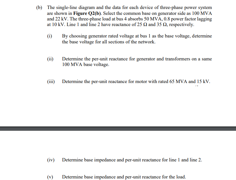
Transcribed Image Text:(b) The single-line diagram and the data for each device of three-phase power system
are shown in Figure Q2(b). Select the common base on generator side as 100 MVA
and 22 kV. The three-phase load at bus 4 absorbs 50 MVA, 0.8 power factor lagging
at 10 kV. Line 1 and line 2 have reactance of 25 N and 35 Q, respectively.
(i)
By choosing generator rated voltage at bus 1 as the base voltage, determine
the base voltage for all sections of the network.
(ii)
Determine the per-unit reactance for generator and transformers on a same
100 MVA base voltage.
(iii)
Determine the per-unit reactance for motor with rated 65 MVA and 15 kV.
(iv) Determine base impedance and per-unit reactance for line 1 and line 2.
Determine base impedance and per-unit reactance for the load.
Expert Solution
This question has been solved!
Explore an expertly crafted, step-by-step solution for a thorough understanding of key concepts.

Step by step
Solved in 4 steps with 3 images

Knowledge Booster


Learn more about
Need a deep-dive on the concept behind this application? Look no further. Learn more about this topic, electrical-engineering and related others by exploring similar questions and additional content below.Recommended textbooks for you
Power System Analysis and Design (MindTap Course …
Electrical Engineering
ISBN:
9781305632134
Author:
J. Duncan Glover, Thomas Overbye, Mulukutla S. Sarma
Publisher:
Cengage Learning
Power System Analysis and Design (MindTap Course …
Electrical Engineering
ISBN:
9781305632134
Author:
J. Duncan Glover, Thomas Overbye, Mulukutla S. Sarma
Publisher:
Cengage Learning