
Concept explainers
Videos
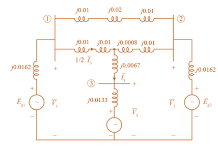
Consider the single-line diagram of the power system shown in Figure 3.38. Equipment ratings are
Generator 1:
Generator 2:
Synchronous motor 3:
Three-phase
Three-phase
Neglecting resistance, transformer phase shift, and magnetizing reactance, draw the equivalent reactance diagram. Use a base of 100 MA and 500 kV for the 50-ohm line. Determine the per-unit reactances.

Trending nowThis is a popular solution!

Chapter 3 Solutions
Power System Analysis and Design (MindTap Course List)


- Consider a single-phase electric system shown in Figure 3.33. Transformers are rated as follows: XY15MVA,13.8/138kV, leakage reactance 10 YZ15MVA,138/69kV, leakage reactance 8 With the base in circuit Y chosen as 15MVA,138kV determine the per-unit impedance of the 500 resistive load in circuit Z, referred to circuits Z, Y, and X. Neglecting magnetizing currents, transformer resistances, and line impedances, draw the impedance diagram in per unit.arrow_forwardPowerWorid Simulator case Problem 3_60 duplicates Example 3.13 except that a resistance term of 0.06 per unit has been added to the transformer and 0.05 per unit to the transmission line. Since the system is no longer lossless, a field showing the real power losses has also been added to the oneline. With the LTC tap fixed at 1.05, plot the real power losses as the phase shift angle is varied from 10 to +10 degrees. What value of phase shift minimizes the system losses?arrow_forwardConsider the oneline diagram shown in Figure 3.40. The three-phase transformer bank is made up of three identical single-phase transformers, each specified by X1=0.24 (on the low-voltage side), negligible resistance and magnetizing current, and turns ratio =N2/N1=10. The transformer bank is delivering 100 MW at 0.8 p.f. lagging to a substation bus whose voltage is 230 kV. (a) Determine the primary current magnitude, primary voltage (line-to-line) magnitude, and the three-phase complex power supplied by the generator. Choose the line-to-neutral voltage at the bus, Va as the reference Account for the phase shift, and assume positive-sequence operation. (b) Find the phase shift between the primary and secondary voltages.arrow_forward
- Figure 3.39 shows a oneline diagram of a system in which the three-phase generator is rated 300 MVA, 20 kV with a subtransient reactance of 0.2 per unit and with its neutral grounded through a 0.4- reactor. The transmission line is 64km long with a cries reactance of 0.5-/km. The three-phase transformer T1 is rated 350MVA.230/20kV with a leakage reactance of 0.1 per unit. Transformer T2 is composed of three single-phase transformers, each rated 100 MVA, 127/13.2kV with a leakage reactance of 0.1 per unit. Two 13.2kV motors M1 and M2 with a subtransient reactance of 0.2 per unit for each motor represent the load. M1 has a rated input of 200 MVA with its neutral grounded through a 0.4- current-limiting reactor, M2 has a rated input of 100 MVA with its neutral not connected to ground. Neglect phase shifts associated with the transformers. Choose the generator rating as base in the generator circuit and draw the positive-sequence reactance diagram showing all reactances in per unit.arrow_forwardWith the same transformer banks as in Problem 3.47, Figure 3.41 shows the oneline diagram of a generator, a step-up transformer bank, a transmission line, a stepown transformer bank, and an impedan load. The generator terminal voltage is 15 kV (line-to-line). (a) Draw the per-phase equivalent circuit, aounting for phase shifts for positive-sequence operation. (b) By choosing the line-to-neutral generator terminal voltage as the reference, determine the magnitudes of the generator current, transmiss ion-line current, load current, and line-to-line load voltage. Also, find the three-phase complex power delivered to the load.arrow_forwardConsider the three single-phase two-winding transformers shown in Figure 3.37. The high-voltage windings are connected in Y. (a) For the low-voltage side, connect the windings in , place the polarity marks, and label the terminals a, b, and c in accordance with the American standard. (b) Relabel the terminals a, b, and c such that VAN is 90 out of phase with Va for positive sequence.arrow_forward
- The per-unit equivalent circuit of two transformers Ta and Tb connected in parallel, with the same nominal voltage ratio and the same reactan of 0.1 per unit on the same base, is shown in Figure 3.43. Transformer Tb has a voltage-magnitude step-up toward the load of 1.05 times that of Ta (that is, the tap on the secondary winding of Tb is set to 1.05). The load is represented by 0.8+j0.6 per unit at a voltage V2=1.0/0 per unit. Determine the complex power in per unit transmitted to the load through each transformer, comment on how the transformers share the real and reactive powers.arrow_forwardDetermine the positive- and negative-sequence phase shifts for the three- phase transformers shown in Figure 3.36.arrow_forwardReconsider Problem 3.64 with the change that now Tb includes both a transformer of the same turns ratio as Ta and a regulating transformer with a 4 phase shift. On the base of Ta, the impedance of the two comp onents of Tb is jO.1 per unit. Determine the complex power in per unit transmitted to the load through each transformer. Comment on how the transformers share the real and reactive pors.arrow_forward
- Consider three ideal single-phase transformers (with a voltage gain of ) put together as three-phase bank as shown in Figure 3.35. Assuming positive-sequence voltages for Va,Vb, and Vc find Va,Vb, and VC. in terms of Va,Vb, and Vc, respectively. (a) Would such relationships hold for the line voltages as well? (b) Looking into the current relationships, express IaIb and Ic in terms of IaIb and Ic respectively. (C) Let S and S be the per-phase complex power output and input. respectively. Find S in terms of S.arrow_forwardConsider Figure 3.25 of the text for a transformer with off-nominal turns ratio. (i) The per-unit equivalent circuit shown in part (c) contains an ideal transformer which cannot be accommodated by some computer programs. (a) True (b) False (ii) In the - circuit representation for real c in part (d), the admittance parameters Y11 and Y12 would be unequal. (a) True (b) False (iii) For complex c, can the admittance parameters be synthesized with a passive RLC circuit? (a) Yes (b) Noarrow_forward1. What are the applications for stripline and microstrip transmission lines? 2. Give 2 examples of characteristic impedance application for each stripline and microstrip transmission lines.arrow_forward
 Power System Analysis and Design (MindTap Course ...Electrical EngineeringISBN:9781305632134Author:J. Duncan Glover, Thomas Overbye, Mulukutla S. SarmaPublisher:Cengage Learning