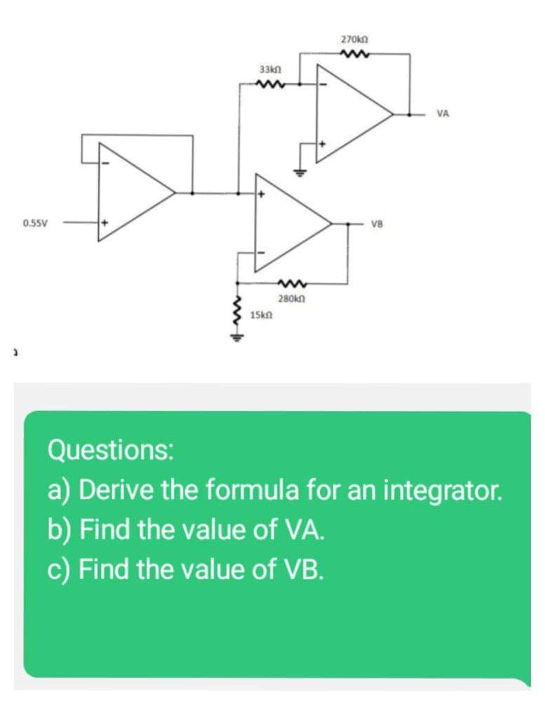
55V www 33kn www 15kn 280kn 270k VB VA Questions: a) Derive the formula for an integrator b) Find the value of VA. c) Find the value of VB.


Q: 3. About Transformer efficiency 3.1. Define efficiency 3.2.State the criterion for maximum…
A: 3.1 Transformer efficiency is defined as the ratio of available output power to input power.…
Q: Using Mesh Analysis, find VA. Round-off to 3 decimal place. Do not include units. Vs1 12V Hilt R₁ 6…
A:
Q: Draw the graphic symbol of a BCD-to-decimal decoder. This is similar to a decoder with 4 inputs and…
A: The BCD-to-decimal decoder is shown below:
Q: Consider the random processes X(t)=A+B cos(t) a Y(t)=A+B sin(t), where A and B are independent and…
A: Since you have posted a question with multiple sub-parts, we will solve first three sub-parts for…
Q: QUESTION 2 A non-inverting amplifier has a 15-k Ry and a 1.2-KOR,. How m 9. 12.5. -12.5. 13.5.
A: Given data, A non-inverting amplifier has Rf=15 kΩRi=1.2 kΩ
Q: The boolean function F=A+A'B+C+C'B' can be minimized to be equal to OA+B+C OA+C 01 00
A: Given function, F=A+A'B+C+C'B'
Q: Consider an aperiodic continuous-time signa x(t) having the corresponding Fourier transform X(jw).…
A: In this question we will find Fourier transform of given signal....
Q: Define the unit step function and the shifted unit step function. Need
A: The unit step function and its shifted counterpart has been defined in the following section.
Q: A 50 kVA, 1100/230 V, distribution transformer has iron loss of 1 kW and full load copper loss of 2…
A:
Q: E (t) = sin 2t R = 1000 L = 4H ww C = 0.01F Figure Q4: RLC circuit + Vo(t)
A:
Q: Consider the feedback control system block diagram in Fig.1
A:
Q: Explain double revolving field theory. A 3-phase delta connected 440 volt, 50Hz, 4-pole induction…
A: Since you have asked multiple questions, we will solve the second question for you. If you want any…
Q: In which of the following configuration a MOSFET does not work as an amplifier? Select one: O a.…
A: An amplifier is an electronic defiance which increases the amplitude of input applied signal. MOSFET…
Q: Draw the waveform generated by the statements below:initial fork w = 0; #10 w = 1; # 40 w = 0; # 20…
A: It is given that: initial forkw = 0; #10 w = 1; # 40 w = 0; # 20 w = 1; #15 w = 0;join
Q: Q6. For the system shown in Figure(5) R(s) K s(s+ 1) (s + 6) (s+4) K C(s) Figure (5) a) The value of…
A:
Q: A 400 V, 3-phase, 4 wire system supplies resistive loads between each of the three lines and…
A: We have an 3-Phase, 4-Wire System That supplies power to the resistive load as shown in figure We…
Q: The state-equations of the control system shown in Fig.1 is:
A: Given: Required: State-space representation of the above closed-loop transfer function
Q: The following readings are obtained when doing a Break test on a d. c. shunt motor: - Spring balance…
A: Reading of DC Shunt motor with, Spring Balance Reading = Tight Side(W1) = 30.5 kg.…
Q: Determine the Thevenin value seen across RL. Round-off to 3 decimal place. Do not include units. R₁…
A:
Q: Given x[n] = au[n] → X(ew) = 1 ______ 1-ae-jw Then the DTFT of x[n] = (²)"u[n] is Select one: O 1…
A:
Q: (b) Figure Q.2(b) shows the power derating curve for a power transistor. It is rated for a maximum…
A: Given : Power dissipation PD is 115 W Case temperature TC is 25°C Derating factor is 0.657 W/°C…
Q: Find the node voltages in the circuit shown in Fig. 13-43 22.5/0° A 30/40° A ¹0 0.5 f jlf 36/15° V
A: Given here a electrical circuit and asked to find the nodal voltages.
Q: Define digital cartographic system?
A: Digital mapping, also known as digital cartography, is the act of compiling and formatting a group…
Q: Simplify the following functions, and implement them with two level NAND gate circuits: F (A, B, C,…
A: It is given that: F (A, B, C, D)=A′B′C′D+CD+AC′D
Q: Y(s) 2. Find the transfer function of Figure 2 U(s) H₂ R₂ H₂ Figure 2 Block diagram of a hydraulic…
A: Transfer function:- It is the ratio of Laplace transform of output to the Laplaxe transform of…
Q: Let the random variable y be characterized by the following density function: fy(v) = 0.28(y + 2) +…
A: Given: the density function for a random variable Y as fY(y)=0.2δ(y+2) + 0.1δ(y) + 0.2δ(y-2) +…
Q: Considering a discrete LTI system, if the input is S[n 1] what would be the output? -
A:
Q: Design a 6-bit ripple carry adder. Experimentally find out the sum of 110011 and 111001. Construct…
A: Here, we have to design 6 bit ripple carry adder. Full adders are used for designing n-bit ripple…
Q: Given x[n] = a¹u[n] ←→ X(ej") = = 1-ae-J Then the DTFT of x[n] = (2-"-3")u[n] is Select one: O…
A:
Q: H(s) = 3. Determine 13s² + 46s + 133 (s + 1)² (s² + 6s + 25) the value of h(0) using the initial…
A:
Q: Equivalent resistance (CLO 2): Determine the value of R2 in the below circuit when REq-10.8 02: om 4…
A: Given circuit:
Q: A system is represented by the transfer function Y(s) R(s) = T(S) The state variable representation…
A: The given transfer function is YsRs=s+3s3+6s2+12s+8. We need to determine the state space…
Q: The switch in figure has been open for a long time. It is closed at t = 0 s. What is the current…
A:
Q: . Determine the value of h(0)
A:
Q: Write a dataflow description of the BCD-to-excess-3 converter using the Boolean expressions listed…
A: The dataflow modelling describes the combinational circuit based on their function. The Excess 3…
Q: For the following circuit, find Vo a. 18.6V b. 19.6V c. 19.3V d. None
A:
Q: PRACTICE PROBLEM 10.12 R www www R Figure 10.34 For Practice Prob. 10.12. -OV Obtain the closed-loop…
A: 10.12) To find the closed-loop gain and phase shift for the circuit given R= 10 k ohm, C = 1 uF,…
Q: +1,0V +36 slokn 5.6kn B = 50, assume VBE) = 0.8V fina VE, VC, VB 1E, ib, ic
A:
Q: Using the equation: X (s)_ _1-6²³² (5+₁) 2 5² a closed-form expression for the clime-domain) output…
A: Time domain provides a picture of how a dynamic system's state evolves over time in response to a…
Q: What is the limit on how many gravity assists a single spacecraft can get?
A: The principle of gravity assist is that the initial velocity of a ship can be multiplied by up to…
Q: QUESTION 5 Calculate the power rating of a three phase system where the phase voltage is 100 Volts…
A: Given, A three phase system has Phase voltage, Vph=100 V Phase current, Iph=10 A
Q: 3) Determine whether or not each of the following continuous-time signals is periodic. If the signal…
A:
Q: A 6 pole generator has a flux of 12 mWb per pole. The armature has a total of 900 conductors and is…
A: We have a generator with, Pole (P) = 6 Flux/pole Ф = 12 mWb = 0.012 Wb…
Q: Find the POS expression that represents the following Karnaugh map: CD AB Select one: a. O b. O C. O…
A: Given: K-Map:
Q: Find out the Laplace transform of the shifted unit step function ult-a). Use the properties of…
A: In this case, the Laplace transform of the shifted unit step function is to be determined.
Q: (a) Find the transfer function for the circuit shown in Figure Q.2a if the input voltage is F) and…
A: Given that Input voltage Vi(s) and output voltage Vo(s). The circuit is shown below.
Q: Solve for the current in the circuit below. 36 با تم 300 12 V 5.00 4.00 لله
A:
Q: B1. An electrical engineer tested a 1 kVA, 240/40 V single phase transformer, and the performance on…
A:
Q: A three-phase balanced load of 15A per phase is supplied by a steel wire armoured cable with a…
A: A three-phase balanced load is supplied with steel wire, Given Data:- mV = 15 Length of cable (L):-…
Q: 1. A balanced Y load has one phase voltage of VBN = 120/130 V. If the phase sequences is ABC, find…
A: In this question, We need to calculate the line voltage if system is balanced star connected. A…
PLEASE ANSWER ALL OF THIS QUESTION ASAP!!!

Step by step
Solved in 5 steps with 5 images


![Digital Modulation Scheme (Amplitude-Shift Keying [ASK], Phase-Shift Keying [PSK], Frequency-Shift Keying [FSK])](/static/compass_v2/subjects/engineering/electrical-engineering.svg)
- Determine the output voltage of an op amp amplifier circuit with the following parameters: Differential voltage gain = 4522CMRR = 631Vi1 = 659 mV Vi2 = 659 mV Vi1 and Vi2 are in phase and have the same frequency. \ QUICKLYSignal-conditioning analysis shows that the following equation must relate output voltage to input voltage: Vout = 3Vin – 3V Design circuits to do this using (a) a summing amplifier and (b) a differential amplifierConsidering the amplifier gain 13 and the number 2 as N, design a Wien Bridge oscillator circuit with an oscillating frequency ((1 + N) × 1000) Hz. Draw the circuit. Show the process steps. Show the values of the circuit elements in your drawing. I would be very happy if you could be quick :)
- An op amp has Rid = 1MΩ, Ro = 100 Ω, and A = 1×10⁴. Can a single-stage amplifier be built with this op amp that meets all of the following specifications? Show which specifications can be met and which cannot. |Av| = 200 Rin ≥108 Ω Rout ≤ 0.2 ΩDesign a Wien Bridge oscillator circuit with an amplifying gain of 13 and an oscillating frequency (5 × 1000) Hz.Draw the circuit. Show the process steps.Show the values of circuit elements in your drawing.Op-amps are ideal, supplied with +/-15V. wma 1st diode approximation. a. Plot Vo(t)b. Plot Ii(t)
- What is the cut–off frequency of an op-amp if the unity-gain frequency is 2.8 MHz and the open-loop gain is 200,000? Show the details of your work. Write your solution on a white typewriting paper, scan it in JPEG format and upload it to the space provided below. ASAP.Find the closed-loop transconductance, input resistance, and output resistance for the circuit as shown. Assume RI = 2.4kΩ, RL = 7.5kΩ, and R1 = 7.5 kΩ.Design a multi-stage amplifier using the specifications below. After the necessary calculations are performed, simulate the circuit in Multisim and make any corrections/changes to the circuit, as necessary. Part I: Amplifier Specifications. • Use no more than three 2N3904 transistors. • The overall amplifier gain should be at least Av = +50 • Input signal should be at • Your circuit load • The input resistance, • The output resistance, . • VCC ≤ 20 volts • The output voltage, Vout is not inverted from the input voltage, Vin.
- Determine the required values of R1, R2, Rc, and RE. Also, determine the expected output voltage if the input voltage is equal to 0.001 Vrms. GIVEN: Zi = 1145.66 ohms Zo = 3.3 Kohms Beta = 80 Vcc = 20V R1 + R2 = 43.7 Kohms Av = 167.43 Ai = 58.13Project # 3 (Use a FET op-amp) You’ve been working with an implementation team to build the following components of a system: The system consists of a DC power supply, filters, instrumentation amplifier, one-state system and A/D converter. Build an AC/DC dual power supply circuit that draws a 55Vp-p sinusoidal voltage, to provide a dc output voltage of +10 V. Find the proper data sheet of the IC regulator and specify ranges of output current and voltage. Full analysis of voltages and currents should be included. What modifications would you recommend to draw more current while maintaining same output voltage? Build a 4th order Butterworth LP filters that cover a signal range 10kHz and a gain of 100V/V each. Use C = 0.01µF with proper values of R’s. Record your findings and include plots (magnitude and phase. Calculate the roll-off of the filter. Build an instrumentation amplifier having a differential gain of 50V/V. Choose the right differential input and common input signals to…What is the cut–off frequency of an op-amp if the unity-gain frequency is 2.8 MHz and the open-loop gain is 200,000? Show the details of your work. Write your solution on a white typewriting paper, scan it in JPEG format and upload it to the space provided below.