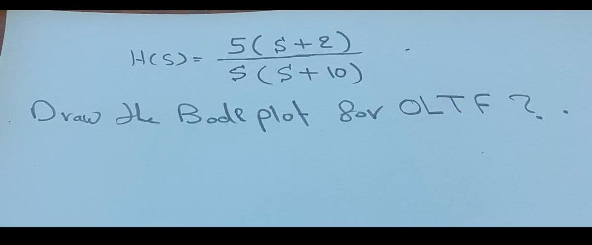
5(s+2) s (St 10) Draw Hhe Bode plot Sor OLTF ?


Q: In an LCR circuit, C-4, H and R-1000. If the circuit is operoting ot resonance frequency the…
A: In the RLC circuit Find the impedance if the circuit is resonance
Q: In Bode diagram the corner frequency of G(jw) = 1 22 - (1+j@T) is: O A) 1/Tw O B) There are not…
A: In this question , we will write corner frequency for given transfer function...
Q: This is for a parallel rlc resonant circuit 1vpk source 1khz 100 ohm resister .047 uf capacitor 100…
A: Parallel R, L and C circuit and its values are –
Q: Quèstion 1 What is the value of the quality factor in the following circuit during resonant…
A: Given circuit:
Q: Design a lag compensator for the system below. The ramp error constant should be Kv 100 and the…
A: Consider the given open-loop transfer function, Gs=50Kss+5s+10 In order to design a lag compensator,…
Q: A parallel RLC resonant circuit has a resistance of 250 ohms. If it is known that the bandwidth is…
A:
Q: Find the resonant frequency for a series RLC circuit where R= 20 2, C= 5.00 µF, and L = 4.00 mH. (2…
A: Given: A series RLC circuit where R=20 ΩC=5 μFL=4 mH
Q: A resistor of 8 ohm, an inductor of 30 mH and a capacitor of 20 uF are connected in series. AC of…
A: Solution: Given data: Resistor R=8 ohm, inductor L=30 mH =30×10-3H capacitor…
Q: A parallel RLC resonant circuit has a resistance of 250 ohms. If it is known that the bandwidth is…
A:
Q: Drzow the bode plot for the onetion and eomment on the Stability of the Systam. k(1+0.013) st3 5(1+)…
A: GS HS = K 1 + 0.01SS1 + S 5 + 0.1S ---- 1) From equation -1) GS HS = K 1 + 0.01S5×S1 + S 1 + 0.15S…
Q: According to the following schematic diagram of a series RLC Filter, you were requested to answer…
A: Since we only answer up to 3 sub-parts, we’ll answer the first 3. Please resubmit the question and…
Q: Q1/ show in details the steps to draw the bode plots for the system with G(s) as follows: k(s+3)…
A:
Q: Hi sketch the Bode plot for Aus I (4;flo.5) Auso- T6
A: Dear student as per our guidelines we are supposed to solve only one question.kindly repost other…
Q: C(s) = 4 R(s) s+2 s2 + 2s + 81 Draw the Bode Diagram (Magnitude (dB) and Phase(deg) for above…
A:
Q: A Darrallel resonant RL C circui't has R =15Kr,L =3mH, C=2OUF Determine: The resonant Frequency The…
A: When components connected in parallel then voltage across the components remain the same but current…
Q: For parallel resonant circuit shown find 1) BW 2) Qp 3) Ve 4) IL and Ie + 5 mA R, 4 kN L 0.1 mH C =…
A:
Q: b) Draw the Bode Plots (both Magnitude and Phase plots) for H2(jw) = 0.05jw +1. ------ TTT TTM
A:
Q: Question 1 What is the transfer function of the following arrangement: C(s) OB Σ R(S) 65²-2 S Sa O…
A:
Q: An RLC resonant circuit has a resonance frequency of 1.5 MHz and bandwidth of 10 kHz. If C = 150 pF,…
A: Given, An RLC resonant circuit has, Resonance frequency, fo=1.5 MHz Bandwidth, B.W.=10 kHz…
Q: Question 9 A parallel RLC resonant circuit has a resistance of 250 ohms. If it is known that the…
A:
Q: For a system whose Bode diagram (magnitude) is shown below Bode Plot 80 60 40 20 -20 -40 -60 -80 101…
A: We need to find out phase angle for given input and given bode plot
Q: For a parallel resonant circuit with R = 2Ω L = 8H, C = 2F, the quality factor is Select one: a.…
A:
Q: (easy) A lead compensator based on Bode Diagram is to be designed, as shown below, and one design…
A:
Q: Part 2: R in Series with Parallel CL Resonant Circuit Derive the following equations (from those…
A:
Q: A parallel resonant circuit has a resistance of 2 kn and half power frequencies of 86 kHz and 90…
A: Choose the correct option Parallel resonat circuit resistance R= 2k ohm Half power frequencies fL =…
Q: Bode Diagram 50 -50 -100 -150 -90 -180 -270 101 10 Frequency (rad/s) 10° 102 10 Magnitude (dB) (Bap)…
A:
Q: In an RLC circuit, if the Neper frequency is 50000, L = 10 mH, and R = 1000, the resonant frequency…
A: Brief description: By the use of given neper frequency we need to calculate the value of unknown…
Q: Suppose we have a series resonant circuit for which B=30 kHz, f 0 =300 kHz and R = 40 Ω .Determine…
A: Given data, The value of B = 30 kHz = 30×103 Hz. The value of frequency f0 = 300 kHz = 300×103 Hz.…
Q: Given the following Bode plot for P(s), determine the R(s) P(s) Y(s) b) Ky, the velocity error…
A:
Q: What is the bandwidth of the following signal if A=8, B=15, C=43, and D=55 M(f) -D -C -B A B C D…
A: Bandwidth is the maximum value on frequency axis till which it has some Amplitude
Q: : For the Bode plots shown in Figure (1), find the values of Gm, Pm, Wp, Wg 60 01 4- 2 Fresquenes…
A: Notes Phase margin calculated at gain cross over frequency Gain margin calculated at phase cross…
Q: find transfer function of H(s)/V(s) please. - A. dH = 6く - JH 1)
A:
Q: 4. Draw the Bode magnitude plot of (Same for all of you). KG(s) = (s+5)(s+ 200) Explain how you come…
A: Given transfer function is -
Q: Q.17: For the circuit shown if RL varies from 5 to 102: 1. Did the value of "R" effect on resonance,…
A: Part (1): The equivalent admittance of the circuit is determined as:…
Q: 16. You have a tuned circuit with a resonant frequency of 3.7 MHz and a quality factor (Q) of 250.…
A: Given: In a tuned circuit, Resonant frequency, fr=3.7 MHz Quality factor, Q=250
Q: Q-6 10 for the system G(s) S(S+1)(0.025+1) 1. Draw bode plots. 2. Is the system stable or not. 3.…
A:
Q: Pls help ASAP. The subject is Electric Networks
A: GIVEN: transfer function Calculate; draw the bode plot ( magnitude and phase plot)
Q: Q.17: For the circuit shown if RL varies from 5 to 100 1. Did the value of "R" effect on resonance,…
A: Part (1): The expression for the equivalent admittance is determined as shown below:…
Q: The following data are given for a three-branch parallel circuit: V = 12 V, R = 82 kΩ, L = 15 mH,…
A:
Q: 12) In a series resonant RLC circuit, what is the impedance at resonant frequency? A) Determined…
A:
Q: Match the given transfer functions with the Bode plots in Figure 8.34 and justify your answer.
A: Consider first transfer function…
Q: 6 For t>0, The resonant frequency is found to be (in rad/s) 12.5 O None of the choices O 1 2.5
A: The solution is given below
Q: 7 In the parallel resonance circuit, R = 250 W, L = 2 mH, and C = 20 mF. The circuit is driven by a…
A: Please correct the value of resistance it should be in ohm not watt R = 250 ohm
Q: A series resonant circuit with R=5Q, L = 10mH, C=10mF the quality Factor * : is
A: Given Data: R = 5 ohm L = 10 mH C = 10 mC
Q: The phase angle of Bode plot for the following open-loop system 1 G(s) = %3D (s+10) equals to: p =…
A: Given G(s) = 1/(s+10) Phase angle
Q: L pomts save A A parallel RLC resonant circuit has a resistance of 250 ohms. If it is known that the…
A:
Q: 8.34: For parallel resonant circuit with fo=2MHz, Q=10 & L=25µH, with maximum input current of 20mA…
A:
Q: - For g(t)=4sin300tt sin 700ttt the Nyquist sampling rate is Hz 1000 500 318.3 700
A:
Q: 5.23 A series L-C-R circuit has a resonant frequency fo, with R= 12, L = 1 H and C= 1 F. If the…
A: According to the question we have to find the value of new resonance frequency.

Step by step
Solved in 3 steps with 3 images


- Bode plot of the function G(s) =(s-2)/(s+2) Required PEN paper Solution WIth full steps ..For a parallel resonant circuit with R = 2Ω L = 8H, C = 2F, the quality factor is Select one: a. 0.5. b. 1. c. 1/√ 2. d. 2.A series R L C circuit has the following parameters: R = 10 Ω, L = 10 mH and C = 100 nF. Find the linear resonant frequency f0 and the angular resonant frequency ω0.
- a)find magnitude of G(iw)b) find angle phase of G(iw)c)plot asymtotic bode diagramA series RLC circuit has the following parameters: R=40 ohms L=2.5 mH C=0.1 uF find out the impedance at resonance and the series resonant frequency.A series R-L-C circuit has the following parameter values, R= 10 ohm, L= 0.01 H, C= 100 mF. The Q factor of tge circuit at resonance is _______
- k=2z1=3z2=8p1=4p2=6draw the bode graph of the transfer function manually on logarithmic paper..Question 02: A) How do you use Kirchhoff's law? What are the limitations of Kirchhoff's law? B) What is resonance in RLC circuit? Define the Q-factor in RLC series circuit.Determine the resonant frequency fr and the magnitude of the impedance |Z| for the circuit below at that frequency. What is the voltage amplitude VL across the inductor at resonance? Data: C1 = 5.0 μF, C2 = 25 μF, L = 50. mH, R = 200 Ω, and Vp = 10. V. fr = kHz |Z| = Ω VL = %
- A tank circuit contains a capacitor and an inductor that produce 30 Ω of reactance at the resonant frequency. The inductor has a Q of 15. The voltage of 277V is connected to the circuit. What is the total circuit current of the resonant frequency? Show your work. a) IT= 0.615 A b) IT= 0.423 A c) IT= 0.846 A d) IT= 0.321 AThe inductance coil in the series resonant circuit is 0.2 H, and the resistance coil is 50 Q. At what capacitance value does resonance occur at 1500 kHz in this circuit? Assuming a 100 V r.m.s. e.m.f. at the source.Calculate the DC voltage across a 1042 Ω load for an RC filter section whose R = 140 Ω and C = 0.40 uF. The DC voltage across the initial filter capacitor is 71.1 V Note: Answers in 2 decimal places, unit in V (no need to write the unit)