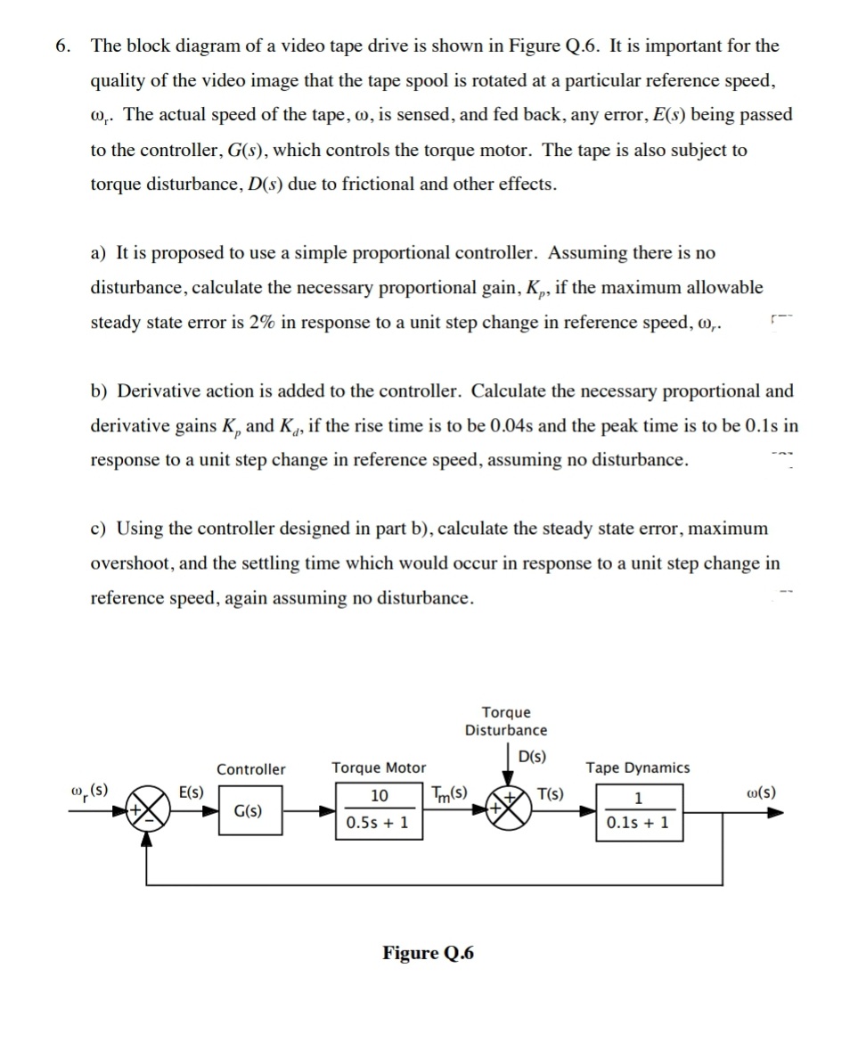
6. The block diagram of a video tape drive is shown in Figure Q.6. It is important for the quality of the video image that the tape spool is rotated at a particular reference speed, w.. The actual speed of the tape, o, is sensed, and fed back, any error, E(s) being passed to the controller, G(s), which controls the torque motor. The tape is also subject to torque disturbance, D(s) due to frictional and other effects. a) It is proposed to use a simple proportional controller. Assuming there is no disturbance, calculate the necessary proportional gain, K,, if the maximum allowable steady state error is 2% in response to a unit step change in reference speed, o,. b) Derivative action is added to the controller. Calculate the necessary proportional and derivative gains K, and K, if the rise time is to be 0.04s and the peak time is to be 0.1s in response to a unit step change in reference speed, assuming no disturbance. c) Using the controller designed in part b), calculate the steady state error, maximum overshoot, and the settling time which would occur in response to a unit step change in reference speed, again assuming no disturbance. Torque Disturbance D(s) Controller Torque Motor Tape Dynamics o, (s) E(s) 10 Tm(s) T(s) 1 o(s) G(s) 0.5s + 1 0.1s + 1 Figure Q.6
6. The block diagram of a video tape drive is shown in Figure Q.6. It is important for the quality of the video image that the tape spool is rotated at a particular reference speed, w.. The actual speed of the tape, o, is sensed, and fed back, any error, E(s) being passed to the controller, G(s), which controls the torque motor. The tape is also subject to torque disturbance, D(s) due to frictional and other effects. a) It is proposed to use a simple proportional controller. Assuming there is no disturbance, calculate the necessary proportional gain, K,, if the maximum allowable steady state error is 2% in response to a unit step change in reference speed, o,. b) Derivative action is added to the controller. Calculate the necessary proportional and derivative gains K, and K, if the rise time is to be 0.04s and the peak time is to be 0.1s in response to a unit step change in reference speed, assuming no disturbance. c) Using the controller designed in part b), calculate the steady state error, maximum overshoot, and the settling time which would occur in response to a unit step change in reference speed, again assuming no disturbance. Torque Disturbance D(s) Controller Torque Motor Tape Dynamics o, (s) E(s) 10 Tm(s) T(s) 1 o(s) G(s) 0.5s + 1 0.1s + 1 Figure Q.6

Power System Analysis and Design (MindTap Course List)
6th Edition
ISBN:9781305632134
Author:J. Duncan Glover, Thomas Overbye, Mulukutla S. Sarma
Publisher:J. Duncan Glover, Thomas Overbye, Mulukutla S. Sarma
Chapter11: Transient Stability
Section: Chapter Questions
Problem 11.17P

Related questions

Question
Transcribed Image Text:6. The block diagram of a video tape drive is shown in Figure Q.6. It is important for the
quality of the video image that the tape spool is rotated at a particular reference speed,
0,. The actual speed of the tape, w, is sensed, and fed back, any error, E(s) being passed
to the controller, G(s), which controls the torque motor. The tape is also subject to
torque disturbance, D(s) due to frictional and other effects.
a) It is proposed to use a simple proportional controller. Assuming there is no
disturbance, calculate the necessary proportional gain, K,, if the maximum allowable
steady state error is 2% in response to a unit step change in reference speed, w,.
b) Derivative action is added to the controller. Calculate the necessary proportional and
derivative gains K, and K, if the rise time is to be 0.04s and the peak time is to be 0.1s in
response to a unit step change in reference speed, assuming no disturbance.
c) Using the controller designed in part b), calculate the steady state error, maximum
overshoot, and the settling time which would occur in response to a unit step change in
reference speed, again assuming no disturbance.
Torque
Disturbance
D(s)
Controller
Torque Motor
Tape Dynamics
", (s)
E(s)
10
Tm(s)
T(s)
1
w(s)
G(s)
0.5s + 1
0.1s + 1
Figure Q.6
Expert Solution
This question has been solved!
Explore an expertly crafted, step-by-step solution for a thorough understanding of key concepts.

Step by step
Solved in 3 steps with 1 images

Knowledge Booster


Learn more about
Need a deep-dive on the concept behind this application? Look no further. Learn more about this topic, electrical-engineering and related others by exploring similar questions and additional content below.Recommended textbooks for you
Power System Analysis and Design (MindTap Course …
Electrical Engineering
ISBN:
9781305632134
Author:
J. Duncan Glover, Thomas Overbye, Mulukutla S. Sarma
Publisher:
Cengage Learning
Power System Analysis and Design (MindTap Course …
Electrical Engineering
ISBN:
9781305632134
Author:
J. Duncan Glover, Thomas Overbye, Mulukutla S. Sarma
Publisher:
Cengage Learning