

Q: In the circuit shown below, a) What is the total current in the circuit and b) What is the power…
A: a) Find the equivalent resistance Equivalent resistance due to 36 Ω & 18 Ω resistors is36 Ω×18…
Q: Consider the circuit shown in the figure below. (Assume R, = 14.5 N and R, = 7.00 N.) 25.0 V R2 R2 R…
A:
Q: For the circuit shown in the figure below, calculate (a) the current through each resistor and (b)…
A:
Q: For the circuit shown, determine the current in the 4.0 Q resistor. A 20 ww 12V ww ww
A:
Q: "For the circuit below, for the total voltage of the system, the voltmeter should be connected at…
A: Dear student Concept: The Voltmeter is a device which keasures the potential difference between two…
Q: Consider the circuit in the figure. 20 Ω 20 N 60 N 10 Ω (a) Find the equivalent resistance of this…
A:
Q: For the following circuit in the figure below, find the power ( in units of Watt) delivered to the…
A: The solution is provided below.
Q: The circuit in the figure contains a cell of emf e and four resistors connected as shown. Let the…
A: This is a concept of current division
Q: For the following circuit in the figure below, find the power ( in units of Watt) delivered to the…
A: Given data: Total Potential difference (ε) = 24.4 V Resistance R = 3 Ω
Q: In the circuit as shown in figure 2 below, calculate: a) The voltage across each resistor b) The…
A:
Q: For the following circuit in the figure below, find the power ( in units of Watt) delivered to the…
A:
Q: Consider the circuit shown in the figure below. (Assume R, 13.5 N and R, 7.50 Ω.) b 25.0 V R2 R2 R E…
A: Given : R1=13.5 Ω R2=7.50 Ω
Q: A professor created the circuit shown in the figure for her lab. Assuming Ɛ = 7.70 V and R = 5.00 N,…
A: Given: R = 5 Ω E = 7.7 V
Q: For the following circuit in the figure below, What is the current ( in units of A) in the 10-Q…
A: Since 5 ohm, 10 ohm and 5 ohm resistors are in parallel, so, calculate their equivalent resistance.…
Q: What I Have Learned In the circuit shown in the figure below, find (a) the current in resistor R;…
A: V1 = 28 volts R1 = 6 ohm I1 = 4 A R2 = 3 ohm I2 = 6 A
Q: Solve the following problems. Show the complete solution. 1. Four resistors are connected to a…
A: R1 = 30.0 ΩR2 = 50.0 ΩR3 = 80.0 ΩR4 = 20.0 ΩVoltage: V = 12 V
Q: Problem 2. For the circuit shown in the figure below, find the current in each resistor and the…
A: Given : V = 40 V R1 = 2 Ω R2 = 5 Ω R3 = 8 Ω
Q: If the resistors in problem 1 were connected as shown below, solve for the: 12 V R2= 42 R,= 2 2 R3=…
A: V=Potential of cell=12 VR1=2 ΩR2=4 ΩR3=6 ΩI=Current
Q: Consider the circuit shown in the figure. Find (a) the current in the 20.0-2 resistor and (b) the…
A:
Q: what different values of resistance can you get by combining three 6(Greek capital omega)…
A: We need to find out the different values of resistances possible, by combining three 6 ohms…
Q: Let us consider the following circuit where two batteries 1=2l V with internal resistance 1=0.3 and…
A: As there is not mentioned that which question to answer therefore according to Bartleby guidelines…
Q: 25.0 V 10.0 N 10.0 N a b 5.00 n 5.00 N
A:
Q: R2 R1 R4 R3 4.0 Ω 2.0 Ω 12 N AV
A: R1 = R3 = 2.8 ohm R2 = R4 = 8.6 ohm ∆V = 13 voltsLet : R5 = 4 ohm R6 = 12 ohm R7 = 2 ohm
Q: Find the current in the 12-N resistor in the figure below. (Assume R, = R3 = 2.2 N, R, = R4 = 6.6 N,…
A:
Q: 2) For the circuit shown below, find (a) I1, I2, and l3 and (b) the current in the 7 Q resistor. 35…
A:
Q: For the circuit shown in the figure below, use KVL to solve for unknown voltages Vc, Ve, VG, VH -…
A: This problem is related to Kirchhoff;s voltage law. Apply KVL law and write the expression.…
Q: Problem 2. For the circuit shown in the figure below, find the current in each resistor and the…
A: Given data: Battery voltage (V) = 40 V All resistors are connected in parallel
Q: The diagram below shows a circuit with two resistors. 8.0 2 8.0 2 12-volt source A What is the…
A: Given data: Two resistors are connected series combination R1 = R2 = 8.0 Ω Battery voltage (V) = 12…
Q: Answer the following Choice and explanation
A:
Q: Calculate the power delivered to each resistor in the circuit shown in the figure below. (Let R, =…
A:
Q: Examine the following circuit diagram showing four resistors connected to a battery. R,=100 0.20 A =…
A:
Q: In the circuit of the figure below, the current I is 2.4 A while the values of E and R are unknown.…
A:
Q: For the following circuit in the figure below, find the power ( in units of Watt) delivered to the…
A: Given, ε = 16.5 V R = 3 ohm
Q: Consider the circuit shown in the figure below. (Assume R, = 16.0 N and R2 = 4.50 N.) b 25.0 V* R R2…
A: SOlution: Given that V = 25 V R1 = 16 Ohm R2 = 4.5 Ohm
Q: 5) For the circuit shown below, find (a) the equivalent resistance and (b) the currents through the…
A:
Q: Find the current in the 12-2 resistor in the figure below. (Assume R, = R3 = 1.6 2, R, = R = 6.8 2,…
A: Given, Resistances, R1=R3=1.6Ω,R2=R4=6.8 Ω,R5=4 Ω,R6=12 Ω,R7=2 Ω Voltage of battery, V=10 V
Q: For the following circuit in the figure below, What is the current (in units of A) in the 10-0…
A: Given Data : The resistance of resistance 1 is given as R1 = 5 Ω. The resistance of resistance 2 is…
Q: 12 13 R1 E2 R3 R2 the circuit shown above, the emf of the batteries and the resistances are listed…
A:
Q: Find the current in the 12-2 resistor in the figure below. (Assume R, = R3 = 2.8 2, R2 = R4 = 8.6 2,…
A:
Q: Three 4.9 Q resistors are connected in series with a 18.0 V battery. Find the following. (a) the…
A: In series arrangement of resistors, equivalent resistance is given by RS=R1+R2+R3+....…
Q: с Consider the circuits shown below. What is the current through each resistor? R = 2 k2 %3D EV, 1.6…
A:
Q: For the following circuit in the figure below, find the power ( in units of Watt) delivered to the…
A:
Q: 15. For the circuits shown in the Figure below the resistors represent the internal resistance of…
A: We will answer the first question since the exact one is not specified. Please resubmit the question…
Q: Consider the circuit shown in the figure below. (Assume R, = 11.0 N and R, = 6.00 N.) 25.0 V R2 R2…
A: The resistor R2 and 20.0 Ω are in a series combination. Thus, equivalent resistance be:
Q: Three resistors with resistances R1 = 0.47 ohm, R2 = 4.41 ohm, %3D %3D and R3 = 7.59 ohm are is…
A: Given :R1=0.47ΩR2=4.41ΩR3=7.59ΩV=12.1 volt
Q: The figure below shows three resistors (R1 = 17.0 n, R2 = 8.10 N, and R3 = 14.5 N) and two batteries…
A:
Q: Consider the circuit shown in the figure below. (Assume R, = 15.5 N and R, = 3.50 N.) b 25.0 V R2 R2…
A:
Q: For the following circuit in the figure below, What is the current ( in units of A) in the 10-2…
A:
Q: For the circuit below, find the following: a. the equivalent resistance of the circuit b. the…
A:
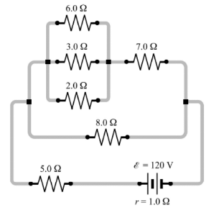
For the circuit shown below, find a.) the equivalent resistance and b.) the currents through the 5Ω, 7Ω, and 3Ω resistors.

Step by step
Solved in 2 steps with 2 images


- The average power at resonance (when Vmax=100 V , R=100 ohm) is: a-99.49W b-45.98W c-49.98W d-94.98WIf the generator cost function of three generators are given as: C1 = 484.8 + 8.47P1 + 0.9P12 (OMR/h/MW) C2 = 471.9 + 7.87P2 + 0.4P22 (OMR/h/MW) C3 = 469.9 + 8.16P3 + 0.62P32 (OMR/h/MW) Find the optimal dispatch of the three generators. Total load demand is 1640 MW. Lambda() Power P1 PowerP2 Power P3How much total energy is dissipated in 1 hour, when you attach 2, 6 Ω light bulbs in series with each other and then connect the combination to a 12 Volt battery? a. 21.1 kJ b. 30 kJ c. 43.2 kJ d. 12 J
- A. 0.87 T B. 1.9 T C. 0.75 T D. 1.2 T E. 0.42 TThe following equations describe an electric circuit. −I1(247 Ω) + 5.80 V − I2(381 Ω) = 0 I2(381 Ω) + I3(150 Ω) − 3.10 V = 0 I1 + I3 − I2 = 0 Calculate the unknowns (in mA). With respect to the 5.8 V battery, consider current moving toward the positive pole as positive and current moving toward the negative pole as negative. THE FOLLOWING GIVEN ANSWERS WERE INCORRECT: I1= -10.008 mA I2= -0.868 mA I3= 0.139 mAOscilloscopes can display ___________________________. (A) just about any electrical signal (B) AC and DC (C) sine waves only (D) DC only (E) AC only
- Answer Q30, 31, 32Consider following circuit with R1 = 62 Ω, R2 = 11 Ω, R3 = 62 / 10 Ω, R4 = 11/10 Ω and and ξ=11 V c. Write Kirchhoff’s potential difference rule for left loop d. Write Kirchhoff’s potential difference rule for right loopCompute for the total energy of the entire circuit. Select one: a. 128.42 micro Joules b. 352.12 micro Joules c. 273.56 micro Joules d. 478.08 micro Joules