7.120 Figure P7.120 shows a scheme for coupling and amplifying a high-frequency pulse signal. The circuit uses two MOSFETS whose bias details are not shown and a 50-Ncoaxial cable. Transistor Q1 operates as a CS amplifier and Q2 as a CG amplifier. For proper operation, transistor Q2 is required to present a 50-2 resistance to the cable. This situation is known as “proper termination" of the cable and ensures that there will be no signal reflection coming back on the cable. When the cable is properly terminated, its input resistance is 50 N. What mustt gm2 be? If Qi is biased at the same point as Q2, what is the amplitude of the current pulses in the drain of Q1? What is the amplitude of the voltage pulses at the drain of Q¡? What value of Rp is required to provide 1-V pulses at the drain of Q2? Rp 50-N coaxial cable Ra- 50n 5 mV nn Figure P7.120
7.120 Figure P7.120 shows a scheme for coupling and amplifying a high-frequency pulse signal. The circuit uses two MOSFETS whose bias details are not shown and a 50-Ncoaxial cable. Transistor Q1 operates as a CS amplifier and Q2 as a CG amplifier. For proper operation, transistor Q2 is required to present a 50-2 resistance to the cable. This situation is known as “proper termination" of the cable and ensures that there will be no signal reflection coming back on the cable. When the cable is properly terminated, its input resistance is 50 N. What mustt gm2 be? If Qi is biased at the same point as Q2, what is the amplitude of the current pulses in the drain of Q1? What is the amplitude of the voltage pulses at the drain of Q¡? What value of Rp is required to provide 1-V pulses at the drain of Q2? Rp 50-N coaxial cable Ra- 50n 5 mV nn Figure P7.120

Introductory Circuit Analysis (13th Edition)
13th Edition
ISBN:9780133923605
Author:Robert L. Boylestad
Publisher:Robert L. Boylestad
Chapter1: Introduction
Section: Chapter Questions
Problem 1P: Visit your local library (at school or home) and describe the extent to which it provides literature...

Related questions
Question
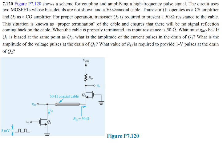
Transcribed Image Text:7.120 Figure P7.120 shows a scheme for coupling and amplifying a high-frequency pulse signal. The circuit uses
two MOSFETS whose bias details are not shown and a 50-2coaxial cable. Transistor Q1 operates as a CS amplifier
and Q2 as a CG amplifier. For proper operation, transistor Q2 is required to present a 50-2 resistance to the cable.
This situation is known as “proper termination" of the cable and ensures that there will be no signal reflection
coming back on the cable. When the cable is properly terminated, its input resistance is 50 2. What must gm2 be? If
Qi is biased at the same point as Q2, what is the amplitude of the current pulses in the drain of Q1? What is the
amplitude of the voltage pulses at the drain of Q1? What value of RD is required to provide 1-V pulses at the drain
of Q2?
DD
Rp
50-N coaxial cable
R2 = 50 2
5 mV nL
Figure P7.120
Expert Solution
This question has been solved!
Explore an expertly crafted, step-by-step solution for a thorough understanding of key concepts.

This is a popular solution!

Trending now
This is a popular solution!

Step by step
Solved in 2 steps

Knowledge Booster


Learn more about
Need a deep-dive on the concept behind this application? Look no further. Learn more about this topic, electrical-engineering and related others by exploring similar questions and additional content below.Recommended textbooks for you
Introductory Circuit Analysis (13th Edition)
Electrical Engineering
ISBN:
9780133923605
Author:
Robert L. Boylestad
Publisher:
PEARSON

Delmar's Standard Textbook Of Electricity
Electrical Engineering
ISBN:
9781337900348
Author:
Stephen L. Herman
Publisher:
Cengage Learning

Programmable Logic Controllers
Electrical Engineering
ISBN:
9780073373843
Author:
Frank D. Petruzella
Publisher:
McGraw-Hill Education
Introductory Circuit Analysis (13th Edition)
Electrical Engineering
ISBN:
9780133923605
Author:
Robert L. Boylestad
Publisher:
PEARSON
Delmar's Standard Textbook Of Electricity
Electrical Engineering
ISBN:
9781337900348
Author:
Stephen L. Herman
Publisher:
Cengage Learning
Programmable Logic Controllers
Electrical Engineering
ISBN:
9780073373843
Author:
Frank D. Petruzella
Publisher:
McGraw-Hill Education

Fundamentals of Electric Circuits
Electrical Engineering
ISBN:
9780078028229
Author:
Charles K Alexander, Matthew Sadiku
Publisher:
McGraw-Hill Education

Electric Circuits. (11th Edition)
Electrical Engineering
ISBN:
9780134746968
Author:
James W. Nilsson, Susan Riedel
Publisher:
PEARSON

Engineering Electromagnetics
Electrical Engineering
ISBN:
9780078028151
Author:
Hayt, William H. (william Hart), Jr, BUCK, John A.
Publisher:
Mcgraw-hill Education,