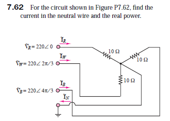
7.62 For the circuit shown in Figure P7.62, find the current in the neutral wire and the real power. TR= 22020 102 ww 10 2 Tr= 2202 21/3 0 10 2 V3= 220 4n/3 o IN
Q: dc steady-state, which, if any, of the following quantities are 0? Select all that apply; pls no…
A: In this we will find which quantities are zero in dc steady state..
Q: 11. What kind of dependent source is this? How do you say so? Explain.
A:
Q: Does transformers work on DC? Justify your answer.
A:
Q: Consider the circuit in the figure. Calculate the voltage v( t) across the capacitor in steady state…
A: To solve the given question, the behavior of the inductor and capacitor in DC circuit should be…
Q: Analyse the steady state error of the system ( I correct the question now please solve it )
A: For the given unity negative feedback system we need to calculate steady state error. Note : It is…
Q: 10. Determine the dc output voltages in Fig. 7. The transformer has a 36V rms secondary voltage…
A: Since we only answer one question at a time. we’ll answer the first question only.Please resubmit…
Q: 7.57 The wire that connects an antenna on your roof to the TV set in your den is a 300-2 wire, as…
A: Here, consider the cable impedance as the source impedance and the impedance of the antenna…
Q: 6 Find the real and reactive power supplied by the source in the circuit shown in Figure P7.26.…
A: Given circuit is – Total impedance is –
Q: Develop an expression for voltage and current traveling on a transmission line assuming all its…
A: we need to develop an expression for voltage and current traveling on a transmission line assuming…
Q: A) A solid specimen of dielectric, dielectric constant of 4.5, shown in the figure has an internal…
A: The given specimen of the dielectric is shown below: If the applied voltage is known, the voltage…
Q: A solenoid is to have an inductance of 0.285 mH, a cross-sectional area of 6.00x10⁻⁴ m2, and a…
A: INDUCTANCE =μ0N2AL SO, N = 0.000285×0.36×101112.57×6 = 1.02X10³
Q: R Vs( the C
A:
Q: For the circuit shown, since IR5 is flowing out of the short circuit, the value of IR5=0 as current…
A: The circuit is,
Q: 7.34 Suppose that the electricity in your home has g out on a hot, humid summer day and the power…
A: The air conditioner consumed power is found below; Average power,PA=V×I×p.fV=120 V,I=9.6…
Q: (a) Considering pure inductance in an ac circuit element, show that the alternating current lags…
A:
Q: he maximum rate of change of potential with distance is obtained when the .direction of the distance…
A: The maximum rate of change of potential with distance is known as potential gradient When the…
Q: Among the cubic lattices in the (001) plane, BCC has the minimal areal density Select one: OTrue…
A: Cubic lattice in the plane 001 , BCC minimal areal density?
Q: Two coils have a mutual inductance of 480mH. One coil is supplied with a current given by I(t) = 3t2…
A: It is Given that:M=480mHIt=3t2-2t-6
Q: 3. Comment on the influence of changing (K) upon steady state error.
A:
Q: Given the waveform of a voltage source shown inFigure P7.8, find:a. The steady DC voltage that would…
A: Part (a) The period of the given wave is 2 s. The heating effect of the wave is decided by the RMS…
Q: a) Briefly explain the terms below and state their unit. i. Period ii. Frequency b) Given that v(t)…
A:
Q: Assume the 8-Ω resistor is the load in the circuitshown in Figure P7.48. Assume vg = 110 V rms and…
A: (a) Let I1 be the current in loop 1, and I2 be the current flowing in loop 2, let V1 be the voltage…
Q: Calculate the phase shifts, de(k), for the hard core potential, V(r) 00, r a. %3D Simplify the…
A: For the hardcore potenctial, V(r) = ∞r<a0r<a Here, we have to simplify for the S-wave.
Q: 2. Identify the location and summarize the purpose of each of the following: а. Piezoelectric…
A: Here it is asked to identify the location and the purpose of each of the given elements. So weed to…
Q: Solve for the steady-state values of the labeled currents at 2 A Va t=0 2 (a) t = 0 iz
A:
Q: If we knew that the transformer shown in FigureP7.49 were to deliver 50 A at 110 V rms with a…
A: Write the given values on the secondary side of the transformer. Find the output power of the load.
Q: What is the mathematical expression of the voltage Vg(t) in the steady (continuous) state?
A:
Q: Find the apparent power and the real powerdelivered to the load in the Y-Δ circuit shown in…
A: In the figure shown above in the circuit is the balanced 3-phase circuit. The voltage source…
Q: A solenoid of length 8 cm has 130 turns of radius 5 cm. a) Ignoring end effects, what is its…
A: Given A solenoid of length 8 cm and 130 turns and 5 cm radius. We need to determine the self…
Q: Answer the following points in detail and rigorously. Instead of resorting to formulas, develop from…
A:
Q: 5 For the circuit of Figure P7.23, determine whether the load is capacitive or inductive for the…
A: The circuit diagram is shown below: In the capacitor, the current leads the voltage, hence it will…
Q: 7.18 A single-phase motor draws 220 W at a power factor of 80 percent (lagging) when connected…
A: The circuit diagram of the motor is shown below: First, we will calculate the equivalent impedance…
Q: Course: Electrical Engineering Subject: Electrical Apparatus Instructions: • Write the GIVEN with…
A:
Q: A. Calculate the expression of the current i(t). B. The time it takes for the current i(t) to reach…
A:
Q: 7. The characteristic equation of a system is given as 3s4+10s3+5s2+23D0. This system is : a) Stable…
A: To find the system
Q: When this resultant voltage is applied to a circuit consisting of a 10-Ω resistor and a capacitance…
A: Here taking voltage as reference, Let the maximum voltage applied is, General expression of voltage…
Q: Q4. The equation relating the current in a circuit with time is i=282.1 sin377t, where the current…
A:
Q: a) Suppose that between the two terminals of an element there is a voltage v (t) and that a current…
A: Note: As per our company guidelines we are supposed to answer ?️only the first 3️⃣ sub-parts. Kindly…
Q: A solid dielectric specimen of dielectric constant of 4.00 has internal void of thickness 0.05 mm.…
A:
Q: C= 6µF Vs= 20V C:= 3µF Figure(Q2a)
A:
Q: 7.77 For the circuit shown in Figure P7.77, find the currents IĄ, Ig, Iç and In, and the real power…
A: From the circuit, Impedance of phase A is, Therefore current,
Q: also like to keep one window air conditioner running, as well as run the refrigerator in your…
A: Given ratings for different appliances, Air conditioner; 9.6 A rms @ 120 V rmsp.f.=0.90 lagging…
Q: Given the sinusoids v1(t) = 8cos (250t +15°) V and v2(t) = 6cos (250t – 45°) V, determine the time…
A: In this question we will find the time by which v2(t) is advanced or delayed with respect to…
Q: 3 The load Z, in the circuit of Figure P7.28 consists of a 25-2 resistor in series with a 0.1-mF…
A: As per our guidelines we can only answer a maximum of three sub-parts at a time. Please resubmit the…
Q: Q5: A transmission line is suspended by a string of four (4) identical insulators of C capacitance…
A:
Trending now
This is a popular solution!
Step by step
Solved in 3 steps with 4 images
- Given the waveform of a voltage source shown in figure P7.8 find: a. The steady DC voltage that would cause the same heating effect across a resistance. b. The average current supplied to a 10-ohm resistor connected across the voltage source. c. The average power supplied to a 1-ohm resistor connected across the voltage source.Given the waveform of a voltage source shown inFigure P7.8, find:a. The steady DC voltage that would cause the sameheating effect across a resistance. b. The average current supplied to a 10-Ω resistorconnected across the voltage source.c. The average power supplied to a 1-Ω resistorconnected across the voltage source.Find the apparent power and the real powerdelivered to the load in the Y-Δ circuit shown in FigureP7.74. What is the power factor? Assume rms values
- For the circuit shown in Figure 7.2, determine apparent power S, real power P, reactive power Qand power factor PF. Also, draw the power triangle.a) Explain the construction of LVDT. Identify some suitable examples according to their applications.b) Discuss contacting and non-contacting tachometers.For the ideal transformer shown in Figure P7.46,consider that vS (t) = 294 cos(377t) V. Finda. Primary current.b. vo(t).c. Secondary power.d. The installation efficiency Pload/Psource.
- In the circuit given belowX=7andY=5Ωas they are defined as;Vvoltage phasoramplitudehow many volts?NOTE: Please enter your answers as 2 digits after the comma.Assuming that a nonzero ac source is applied, state whether the power and reactive power are positive, negative, or zero for a. a pure resistance; b. a pure inductance; c. a pure capacitanceWhat is the mathematical expression of the voltage Vg(t) in the steady (continuous) state?
- Assume that steady state DC conditions exist. A. Determine the energy stored in each capacitor and every inductor. & B. Verify power balance in the circuit, namely power generated by the source equals the power absorbed by the circuit elements.a)i2(t)=? b)Calculate the complex power on the inductance?Compute the average power dissipated by the load seen by the voltage source in figure P7.6. Let omega = 377 rad/s, V_s = 50<0, R = 10 ohm, L = 0.08H, and C = 200 microFarads.