705. Compute the reaction R and sketch the shear and moment diagrams for the propped beam shown in Fig. P-705. Ans. R woL/10 use area moment method wo Figure P-705 R.
705. Compute the reaction R and sketch the shear and moment diagrams for the propped beam shown in Fig. P-705. Ans. R woL/10 use area moment method wo Figure P-705 R.

Chapter9: Application Of Influence Lines
Section: Chapter Questions
Problem 15P

Related questions

Question
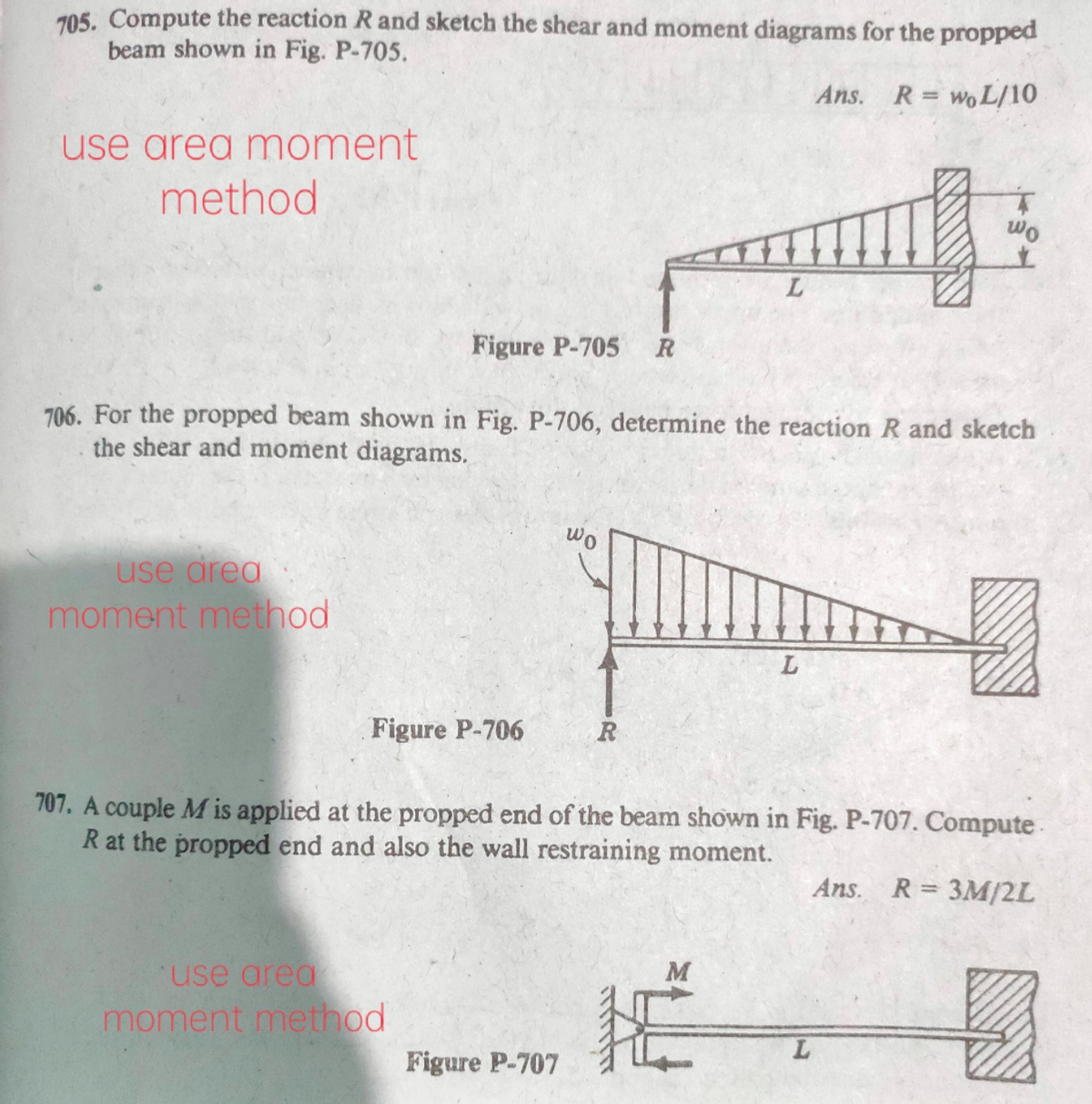
Transcribed Image Text:705. Compute the reaction Rand sketch the shear and moment diagrams for the propped
beam shown in Fig. P-705.
Ans. R= woL/10
use area moment
method
wo
Figure P-705
706. For the propped beam shown in Fig. P-706, determine the reaction R and sketch
the shear and moment diagrams.
wo
use area
moment method
Figure P-706
R
707. A couple M is applied at the propped end of the beam shown in Fig. P-707. Compute
R at the propped end and also the wall restraining moment.
Ans. R= 3M/2L
use area
M
moment method
Figure P-707
Expert Solution
This question has been solved!
Explore an expertly crafted, step-by-step solution for a thorough understanding of key concepts.

Step by step
Solved in 5 steps with 5 images

Knowledge Booster


Learn more about
Need a deep-dive on the concept behind this application? Look no further. Learn more about this topic, civil-engineering and related others by exploring similar questions and additional content below.Recommended textbooks for you