75N 100N 30N/m Mp= 20N.m 10N.m=MA 2m 2m 3m 2m A B D E Figure 3. a) Determine the reaction force at B and E. b) Draw the shear diagram. c) Draw the moment diagram. d) Determine zero-moment point on the beam between A and C.
75N 100N 30N/m Mp= 20N.m 10N.m=MA 2m 2m 3m 2m A B D E Figure 3. a) Determine the reaction force at B and E. b) Draw the shear diagram. c) Draw the moment diagram. d) Determine zero-moment point on the beam between A and C.

Chapter9: Application Of Influence Lines
Section: Chapter Questions
Problem 11P

Related questions

Question
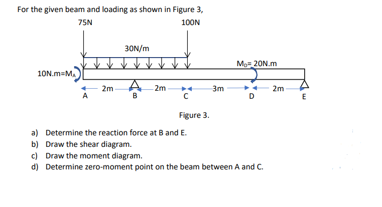
Transcribed Image Text:For the given beam and loading as shown in Figure 3,
75N
100N
30N/m
Mp= 20N.m
10N.m=MA
2m
2m
3m
2m
E
Figure 3.
a) Determine the reaction force at B and E.
b) Draw the shear diagram.
c) Draw the moment diagram.
d) Determine zero-moment point on the beam between A and C.
Expert Solution
This question has been solved!
Explore an expertly crafted, step-by-step solution for a thorough understanding of key concepts.

This is a popular solution!

Trending now
This is a popular solution!

Step by step
Solved in 3 steps with 2 images

Knowledge Booster


Learn more about
Need a deep-dive on the concept behind this application? Look no further. Learn more about this topic, civil-engineering and related others by exploring similar questions and additional content below.Recommended textbooks for you